In this Arduino tutorial you will learn how to control an RGB LED with a potentiometer. First using only digitalWrite(), to get an idea of what we’re doing, and then with a more complex computation and analogWrite(), so we can get any color we want.
If you’re not familiar with how to use a potentiometer yet, check out this Arduino potentiometer tutorial first.
And now let’s get started!
Table of Contents
Arduino circuit with RGB LED and potentiometer
To build the circuit, you will need:
- Arduino board – I use Arduino Uno, but any board where you have at least 3 PWM compatible digital pins, and one analog pin, is fine.
- Breadboard.
- Some male-female wires.
- RGB LED.
- 3 * 220 Ohm resistors.
- Potentiometer.
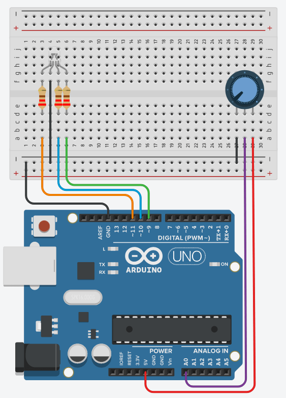
Here is the circuit.
You are learning how to use Arduino to build your own projects?
Check out Arduino For Beginners and learn step by step.
To build the circuit:
- Make a common ground by connecting a GND pin of the Arduino, to the “minus” line of the breadboard.
- For the RGB LED:
- Find the longer leg. Depending on your RGB LED, this can be a cathode or an anode. How to find out? Simply check the manual or description of what you’ve bought. If no instructions, you can first try the “cathode mode” and see if it works. So, if it’s a cathode, plug this to the ground (GND). If it’s an anode, plug it to 5V on the Arduino.
- The 3 other legs correspond to red, blue, and green colors. Connect each of these legs to a PWM compatible digital pin on the Arduino (with a “~” next to the number, like on the picture). Add a 220 Ohm resistor in between for each leg.
- For the potentiometer:
- Connect one of the extreme leg (for example left) to the ground. The other extreme leg should be connected to 5V on the Arduino.
- Connect the middle leg to an analog pin.
Control the RGB LED with the potentiometer – digitalWrite() – 7 colors
In this first application, we are going to modify the color of the RGB LED when we turn the potentiometer knob.
You can see the RGB LED as a combination of 3 different LEDs that you control separately.
We are going to use digitalWrite() – LED fully powered on/off, which means that we have a combination of 7 colors:
- red
- blue
- green
- red + blue
- red + green
- blue + green
- red + blue + green
Let’s write the code for that.
#define RGB_RED_PIN 11
#define RGB_BLUE_PIN 10
#define RGB_GREEN_PIN 9
#define POTENTIOMETER_PIN A0

void digitalWriteRGB(byte red, byte blue, byte green)
{
  digitalWrite(RGB_RED_PIN, red);
  digitalWrite(RGB_BLUE_PIN, blue);
  digitalWrite(RGB_GREEN_PIN, green);
}

void setup()
{
  pinMode(RGB_RED_PIN, OUTPUT);
  pinMode(RGB_BLUE_PIN, OUTPUT);
  pinMode(RGB_GREEN_PIN, OUTPUT);
}

void loop()
{
  int potentiometerValue = analogRead(POTENTIOMETER_PIN);
  int mode = map(potentiometerValue, 0, 1023, 0, 6);

  switch (mode) {
    case 0:
      digitalWriteRGB(HIGH, LOW, LOW);
      break;
    case 1:
      digitalWriteRGB(LOW, HIGH, LOW);
      break;
    case 2:
      digitalWriteRGB(LOW, LOW, HIGH);
      break;
    case 3:
      digitalWriteRGB(HIGH, HIGH, LOW);
      break;
    case 4:
      digitalWriteRGB(HIGH, LOW, HIGH);
      break;
    case 5:
      digitalWriteRGB(LOW, HIGH, HIGH);
      break;
    case 6:
      digitalWriteRGB(HIGH, HIGH, HIGH);
      break;
    default:
      digitalWriteRGB(LOW, LOW, LOW);
      break;
  }
}
Let’s now analyze this code.
Setup RGB and potentiometer pins
#define RGB_RED_PIN 11
#define RGB_BLUE_PIN 10
#define RGB_GREEN_PIN 9
#define POTENTIOMETER_PIN A0
At first, as a best practice, we create a define for each pin we are going to use. One for the potentiometer, and one for each color of the LED – we write the code as if we were controlling 3 different LEDs.
void setup()
{
  pinMode(RGB_RED_PIN, OUTPUT);
  pinMode(RGB_BLUE_PIN, OUTPUT);
  pinMode(RGB_GREEN_PIN, OUTPUT);
}
In the void setup(), we initialize all LEDs (in fact, the 3 legs of the RGB LED) to OUTPUT mode. Nothing to do for the potentiometer, as an analog pin is already in input mode by default.
digitalWriteRGB() function
void digitalWriteRGB(byte red, byte blue, byte green)
{
  digitalWrite(RGB_RED_PIN, red);
  digitalWrite(RGB_BLUE_PIN, blue);
  digitalWrite(RGB_GREEN_PIN, green);
}
This function will help us reduce the code we write in the following.
Every time you need to change the color of the RGB LED, you will need to call digitalWrite() 3 times. By calling this function, instead of 3 redundant lines, you just have one line, which is digitalWriteRGB() with 3 parameters.
Read potentiometer and choose a mode
void loop()
{
  int potentiometerValue = analogRead(POTENTIOMETER_PIN);
  int mode = map(potentiometerValue, 0, 1023, 0, 6);
In the void loop(), we first read the potentiometer’s value with analogRead(). This gives us a value between 0 and 1023.
Because we want to choose between 7 different options, we use the map() function to transform this value from the range 0-1023 to the range 0-6. Note: in programming we usually start to count from 0, not 1.
So now we have a “mode” from 0 to 6. With this value we will be able to choose the corresponding color for the RGB LED.
Power on the RGB LED depending on the potentiometer’s value
  switch (mode) {
    case 0:
      digitalWriteRGB(HIGH, LOW, LOW);
      break;
    case 1:
      digitalWriteRGB(LOW, HIGH, LOW);
      break;
    case 2:
      digitalWriteRGB(LOW, LOW, HIGH);
      break;
    case 3:
      digitalWriteRGB(HIGH, HIGH, LOW);
      break;
    case 4:
      digitalWriteRGB(HIGH, LOW, HIGH);
      break;
    case 5:
      digitalWriteRGB(LOW, HIGH, HIGH);
      break;
    case 6:
      digitalWriteRGB(HIGH, HIGH, HIGH);
      break;
    default:
      digitalWriteRGB(LOW, LOW, LOW);
      break;
  }
}
We use a switch structure to choose a different color depending on the mode we computed. Note: you could also have used an if/else if structure here.
As you can see, each case corresponds to a different color combination that we’ve previously defined.
We also add a default statement, which is a best practice when using a switch.
Control the RGB LED with potentiometer – analogWrite() – 1536 colors
Side note: We will work with 1536 colors, but we won’t get exactly 1536 values. The value we read from the potentiometer is in the range 0-1023. We can map this to 0-1536, or even bigger, but in the end, we will only have 1024 different values. So, in the range 0-1536, some of the values in between are going to be skipped. But for this kind of application we don’t really care about such a precision. I just added this for the completeness of the explanation. Now, back to the tutorial.
The RGB colors we are going to use
How could you possibly map all the 1024 values you get from the potentiometer, to get as many colors as possible with the RGB LED? And even better, how to make those values follow the “rainbow colors”?
To check which values we are going to set, I used this RGB color chart, where you can select different colors with different cursors.

On the left panel, put the cursor to the maximum upper right point. This is going to reduce the number of possible colors to 1536.
Then, move the cursor shown by the second arrow. You will see all the values you can get on the “R”, “G”, and “B”. Those are the values we are going to use (no need to use “H”, “S”, and “V” for this tutorial).
When you move the cursor from up to down, you will see the following:
- red is 255, blue is increasing from 0 to 255.
- blue is 255, red is decreasing from 255 to 0.
- blue is 255, green is increasing from 0 to 255.
- green is 255, blue is decreasing from 255 to 0.
- green is 255, red is increasing from 0 to 255.
- red is 255, green is decreasing from 255 to 0.
So, we have 6 different steps for changing the color. The total amount is 256 * 6 = 1536. Also, you can note that the first color and the last color are the same (red).
Now, let’s put that into code.
The code
#define RGB_RED_PIN 11
#define RGB_BLUE_PIN 10
#define RGB_GREEN_PIN 9
#define POTENTIOMETER_PIN A0

void setup()
{
  pinMode(RGB_RED_PIN, OUTPUT);
  pinMode(RGB_BLUE_PIN, OUTPUT);
  pinMode(RGB_GREEN_PIN, OUTPUT);
}

void loop()
{
  int potentiometerValue = analogRead(POTENTIOMETER_PIN);
  int rgbValue = map(potentiometerValue, 0, 1023, 0, 1535);

  int red;
  int blue;
  int green;

  if (rgbValue < 256) {
    red = 255;
    blue = rgbValue;
    green = 0;
  }
  else if (rgbValue < 512) {
    red = 511 - rgbValue;
    blue = 255;
    green = 0;
  }
  else if (rgbValue < 768) {
    red = 0;
    blue = 255;
    green = rgbValue - 512;
  }
  else if (rgbValue < 1024) {
    red = 0;
    blue = 1023 - rgbValue;
    green = 255;
  }
  else if (rgbValue < 1280) {
    red = rgbValue - 1024;
    blue = 0;
    green = 255;
  }
  else {
    red = 255;
    blue = 0;
    green = 1535 - rgbValue;
  }

  analogWrite(RGB_RED_PIN, red);
  analogWrite(RGB_BLUE_PIN, blue);
  analogWrite(RGB_GREEN_PIN, green);
}
Run this code and turn the potentiometer knob from start to end. You will see all the colors from the rainbow!
Now let’s explain this code step by step.
Setup RGB and potentiometer pins
#define RGB_RED_PIN 11
#define RGB_BLUE_PIN 10
#define RGB_GREEN_PIN 9
#define POTENTIOMETER_PIN A0

void setup()
{
  pinMode(RGB_RED_PIN, OUTPUT);
  pinMode(RGB_BLUE_PIN, OUTPUT);
  pinMode(RGB_GREEN_PIN, OUTPUT);
}
This is exactly the same as before. We create one define per pin, and we set the mode for the 3 RGB legs to OUTPUT.
Read and map potentiometer’s value
void loop()
{
  int potentiometerValue = analogRead(POTENTIOMETER_PIN);
  int rgbValue = map(potentiometerValue, 0, 1023, 0, 1535);
Once again, we read the potentiometer’s value with the analogRead() function.
We then map this value to the range 0-1535 (see the explanation above on RGB colors).
Select a different color for each value
  int red;
  int blue;
  int green;

  if (rgbValue < 256) {
    red = 255;
    blue = rgbValue;
    green = 0;
  }
  else if (rgbValue < 512) {
    red = 511 - rgbValue;
    blue = 255;
    green = 0;
  }
  else if (rgbValue < 768) {
    red = 0;
    blue = 255;
    green = rgbValue - 512;
  }
  else if (rgbValue < 1024) {
    red = 0;
    blue = 1023 - rgbValue;
    green = 255;
  }
  else if (rgbValue < 1280) {
    red = rgbValue - 1024;
    blue = 0;
    green = 255;
  }
  else {
    red = 255;
    blue = 0;
    green = 1535 - rgbValue;
  }
This is the most important part of the program. It may look like it’s complex, but actually, not that much.
You can first see that we have 6 blocks, which correspond to the 6 steps we previously defined. Now, for each step, we apply different rules.
For example, for the 1st step: we set red to 255, and we increase the blue color from 0-255, according to the rgbValue we computed (in the range 0-1535).
If the rgbValue is more than 255, we go to step number 2. Now we have values from 256 to 511. We set blue to 255, and then decrease the red value. To do so, we need to subtract the rgbValue to the max value for this block, which is 511. As an example, if we enter the if structure with rgbValue = 400, then we have red = 511 – 400 = 111.
For step number 3, we keep blue to 255, and this time we increase green. The rgbValue is now between 512 and 767. So, to start from 0 and get to 255, we subtract 512 to each value we get.
Steps number 4, 5, and 6 are following the same logic as the previous steps.
Now, we have 3 values between 0-255, stored into 3 different variables.
Apply the color to the RGB LED
  analogWrite(RGB_RED_PIN, red);
  analogWrite(RGB_BLUE_PIN, blue);
  analogWrite(RGB_GREEN_PIN, green);
}
After the computation, we use analogWrite() on each leg of the RGB – like if it were 3 different LEDs, with the corresponding values for red, blue, and green.
analogWrite() takes a value in the range 0-255, which is exactly what we have computed.
Going further with the potentiometer and RGB LED
In this Arduino tutorial you have learnt how to control an RGB LED with a potentiometer.
The RGB LED has actually 256 * 256 * 256 = 16+ millions possible colors. With one potentiometer, you get 1024 values, which means that you can only get a fraction of the colors. In most situations this may be fine, as you don’t necessarily need a huge precision for your project.
But if you need more colors, or if you just want to experiment more, what you can do is to put 3 potentiometers in your circuit. Each potentiometer will control only one color. In this case, the hardware setup is a bit bigger, but the code would be much simpler. For each potentiometer, you get one value in the range 0-1023, you map this value to 0-255, and apply it to one leg of the RGB LED, that’s it.