In this tutorial I will show you how to setup and use an IR (InfraRed) remote controller with Arduino.
You will learn how to map each button of the controller to a specific action, so you can make your Arduino programs more dynamic.
After reading this post you will be able to fully integrate any IR remote controller to any of your Arduino projects.
Table of Contents
Arduino circuit with IR receiver and IR remote controller
For the circuit you will need:
- Arduino board (any version is fine, I will use Arduino Uno).
- breadboard.
- IR receiver. This will receive data from the remote controller and send it to the Arduino board.
- IR remote controller.
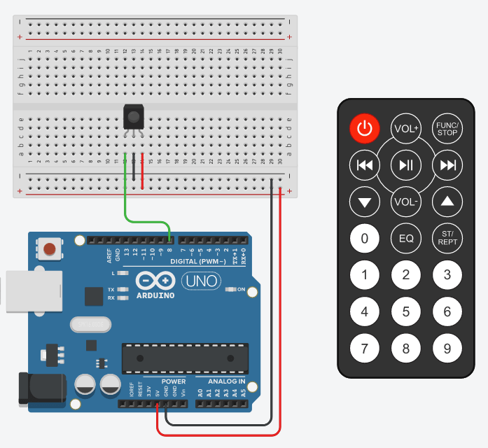
To build the circuit:
You are learning how to use Arduino to build your own projects?
Check out Arduino For Beginners and learn step by step.
- Place the IR receiver on the breadboard, with each pin on an independent line, so they are not connected with each other.
- Connect the GND pin of the IR receiver to one GND pin of the Arduino.
- Connect the Vcc or power pin of the IR receiver to the 5V pin of the Arduino.
- For the data pin, connect it to one digital pin of the Arduino (here digital pin number 8).
(more info on Arduino Uno pins)
Note that the IR receiver you have may be different from the one you see here on the picture. The order of the pins can also be different. The important thing is to locate first GND, Vcc, and data pins, and then connect them accordingly to the correct Arduino pins.
Install an Arduino library for the IR remote controller
Be reassured: you won’t have to write hundreds of lines of code to be able to decode the data you get from the IR receiver. Someone already did that for you. All you need to do is to install an Arduino library and use it.
To do that, open the Arduino IDE. Go to Tools > Manage Libraries.
You will get a new window, where you will see many available libraries that you can install. In the search bar, type “irremote”.
You will find this IRremote library (by shirrif, z3t0, ArminJo).

Select the latest version (whatever version is fine, it doesn’t have to be exactly the same as the one you see on the screenshot). The important thing is to have a version starting by at least 3. Don’t use version 2.
Click on “Install” and wait a few seconds. Then you can close the window, and restart the Arduino IDE.
The IRremote library is now installed and ready to be used!
(if you want to download a specific library version not available from the Arduino IDE, you can also directly get the library from GitHub)
Read data from the IR remote controller
Here is the code to print the corresponding data for each button you press.
#include <IRremote.h>

#define IR_RECEIVE_PIN 8

void setup() {
  Serial.begin(9600);
  IrReceiver.begin(IR_RECEIVE_PIN);
}

void loop() {
  if (IrReceiver.decode()) {
    IrReceiver.resume();
    Serial.println(IrReceiver.decodedIRData.command);
  }
}
Let’s break this down line by line.
#include <IRremote.h>

#define IR_RECEIVE_PIN 8
First you need to include the library you’ve just installed. We also use a define for the data pin of the IR receiver.
void setup() {
  Serial.begin(9600);
  IrReceiver.begin(IR_RECEIVE_PIN);
}
In the void setup() function, we initialize the Serial communication and the IR receiver. For the IR receiver, you use the begin() function with one argument: the number of the data pin for the IR receiver.
void loop() {
  if (IrReceiver.decode()) {
    IrReceiver.resume();
    Serial.println(IrReceiver.decodedIRData.command);
  }
}
In the void loop() function, we continuously check if some new data is available with IrReceiver.decode(). If yes, we immediately call IrReceiver.resume() so that the sensor will continue to read data – if you don’t do this you will get weird errors.
And to get access to the data, we need to use IrReceiver.decodedIRData.command.
If you run this program on your Arduino, and open the Serial Monitor, you’ll see something like this:
12
24
94
28
For each button you press, you’ll get a number.
Map each button to a number
Now we need to map each button to a number, and save that into our program, so we can recognize which button was actually pressed.
Because with just the previous code, well, what does “12” means? In my specific case, “12” means that I pressed on the button “1” of the remote controller.
Here I’m going to show you the step by step process to map each button you want to use, to an actual number in your code.
Important note: each remote controller will produce different numbers. I got “12” for button “1” but you’re probably going to have something different for each controller you try.
Watch this video as an additional resource to this tutorial (steps 1-2-3 for mapping buttons):
After watching the video, subscribe to the Robotics Back-End Youtube channel so you don’t miss the next tutorials!
Step 1: Setup – Print number for the buttons you want
Let’s use the same code we wrote just before.
Run the code on your Arduino and open the Serial Monitor.
For each button you want to use in your application, press the button and write down the number you get.
In my case, here is what I get:
- 12: button 1
- 24: button 2
- 94: button 3
- 64: button play/pause
Etc etc. Do this for each button you need. And once again, you will certainly have different values than me.
Step 2: Add the numbers into your program
Once you know what are the numbers for each button you’re going to use, add some defines at the top of your program.
#include <IRremote.h>

#define IR_RECEIVE_PIN 8

#define IR_BUTTON_1 12
#define IR_BUTTON_2 24
#define IR_BUTTON_3 94
#define IR_BUTTON_PLAY_PAUSE 64

...
Now, you don’t need to worry about the numbers anymore, you can just use IR_BUTTON_1 when you want to use button 1.
Step 3: Write your application program
After you’ve done the setup, you don’t need to print the number every time on the Serial monitor. You can remove the unneeded lines and write your application, using for example a switch structure.
#include <IRremote.h>

#define IR_RECEIVE_PIN 8

#define IR_BUTTON_1 12
#define IR_BUTTON_2 24
#define IR_BUTTON_3 94
#define IR_BUTTON_PLAY_PAUSE 64

void setup() {
  Serial.begin(9600);
  IrReceiver.begin(IR_RECEIVE_PIN);
}

void loop() {
  if (IrReceiver.decode()) {
    IrReceiver.resume();
    int command = IrReceiver.decodedIRData.command;
    switch (command) {
      case IR_BUTTON_1: {
        Serial.println("Pressed on button 1");
        break;
      }
      case IR_BUTTON_2: {
        Serial.println("Pressed on button 2");
        break;
      }
      case IR_BUTTON_3: {
        Serial.println("Pressed on button 3");
        break;
      }
      case IR_BUTTON_PLAY_PAUSE: {
        Serial.println("Pressed on button play/pause");
        break;
      }
      default: {
        Serial.println("Button not recognized");
      }
    }
  }
}
As you can see, for each button we have mapped, we add one more block of code in the switch.
When you press on a button, the IR receiver will send the corresponding number to the Arduino. Then in your code, you get the data with IrReceiver.decodedIRData.command. And then, in the switch, depending on which value you have, you will execute a different action.
If you run the code and press on some buttons, you’ll get something like this in the Serial Monitor.
Pressed on button 1
Pressed on button 2
Pressed on button 3
Pressed on button 3
Button not recognized
Pressed on button play/pause
Now, you can use this code structure as a template for any project you do with an IR remote controller. Just remember to repeat steps 1 and 2 for each new controller you use, because you’re going to have different numbers for the buttons.
You can also decide to use an “if/else if/else” structure instead of the switch. This will work the same, but it’s maybe a bit cleaner with the switch.
Application example: blink some LEDs with the IR remote controller
In this application, what we want to do is simply to toggle a red LED when we press on button 2, and toggle a green LED when we press on button play/pause.
Circuit
Let’s build this circuit.
We use the same circuit as before, and add 2 LEDs:
- For each LED, plug the shorter leg to GND.
- plug the longer leg to a 220Ohm resistor.
- Connect the other leg of the resistor to pin 12 (red LED) and pin 11 (green LED).
Code
Here is the code for the application.
#include <IRremote.h>

#define IR_RECEIVE_PIN 8

#define IR_BUTTON_2 24
#define IR_BUTTON_PLAY_PAUSE 64

#define RED_LED_PIN 12
#define GREEN_LED_PIN 11

byte redLedState = LOW;
byte greenLedState = LOW;

void setup() {
  IrReceiver.begin(IR_RECEIVE_PIN);
  pinMode(RED_LED_PIN, OUTPUT);
  pinMode(GREEN_LED_PIN, OUTPUT);
}

void loop() {
  if (IrReceiver.decode()) {
    IrReceiver.resume();
    int command = IrReceiver.decodedIRData.command;
    switch (command) {
      case IR_BUTTON_2: {
        redLedState = (redLedState == LOW) ? HIGH : LOW;
        digitalWrite(RED_LED_PIN, redLedState);
        break;
      }
      case IR_BUTTON_PLAY_PAUSE: {
        greenLedState = (greenLedState == LOW) ? HIGH: LOW;
        digitalWrite(GREEN_LED_PIN, greenLedState);
        break;
      }
      default: {
        // do nothing
      }
    }
  }
}
If you run this, and press on button “play/pause”, you will see the green LED powered on. If you press again, the green LED will be powered off. Etc. The same applies for the red LED when you press on the button “2”.
And let’s now break the code down.
#include <IRremote.h>

#define IR_RECEIVE_PIN 8

#define IR_BUTTON_2 24
#define IR_BUTTON_PLAY_PAUSE 64
As we have already mapped the buttons, we reuse the same defines we previously wrote. Here we just need buttons “2” and “play/pause” so I’ve only included the numbers for those 2 buttons.
#define RED_LED_PIN 12
#define GREEN_LED_PIN 11

byte redLedState = LOW;
byte greenLedState = LOW;
We set some defines for the LED’s pin numbers. We also keep the state of both LEDs in a global variable, so we will be able to retrieve and toggle this state.
void setup() {
  IrReceiver.begin(IR_RECEIVE_PIN);
  pinMode(RED_LED_PIN, OUTPUT);
  pinMode(GREEN_LED_PIN, OUTPUT);
}
In the setup() we initialize the IR receiver component, and the 2 LEDs with pinMode() function and OUTPUT mode.
void loop() {
  if (IrReceiver.decode()) {
    IrReceiver.resume();
    int command = IrReceiver.decodedIRData.command;
    switch (command) {
This is exactly the same as what we did before. We check if there is some data to read from the IR receiver. If yes, we get the data, we resume the sensor, and we check which button was pressed with a switch structure.
      case IR_BUTTON_2: {
        redLedState = (redLedState == LOW) ? HIGH : LOW;
        digitalWrite(RED_LED_PIN, redLedState);
        break;
      }
When the button “2” is pressed, we toggle the LED state with a one-liner: (redLedState == LOW) will be evaluated to true or false. If it’s true (variable is LOW), we set the variable to HIGH, and if it’s false (variable is HIGH), we set the variable to LOW.
After that we apply the new state to the LED with digitalWrite().
That’s it! If you know how to toggle an LED, and how to get data from an IR receiver, combining the 2 together is really easy.
      case IR_BUTTON_PLAY_PAUSE: {
        greenLedState = (greenLedState == LOW) ? HIGH: LOW;
        digitalWrite(GREEN_LED_PIN, greenLedState);
        break;
      }
We do the same thing for the green LED, when we press on the “play/pause” button.
      default: {
        // do nothing
      }
    }
  }
}
And finally we have the switch default, which we don’t use here.
Conclusion – Arduino IR remote controller
In this tutorial you have seen how to integrate an IR remote controller to make your application more dynamic.
To recap:
- First build the circuit with an IR receiver. One of the pins contains the data, which you are going to connect to a digital pin on your Arduino board.
- Then, you need to map each button so you can know on what you’ve pressed in your code. To map the buttons, first upload a program to print the numbers you get. Create some defines to map those numbers to existing buttons – you will need to repeat this step for each new remote controller you use.
- Remove the printing number code, and write your application using the defines. In the void loop() function, you can use a switch structure to do a different action for each button.