What is the Arduino INPUT_PULLUP option for the pinMode function?
In this tutorial I will show you different examples, using an Arduino board and a simple push button, to explain what INPUT_PULLUP does, and how to use it in your Arduino programs.
And… Let’s get started!
Table of Contents
Quick recap about pinMode
With Arduino you can use digital pins to either read (binary) data from a sensor, or write (binary) data to an actuator.
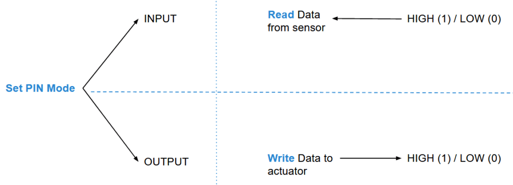
It’s quite simple. Either you set the pin as:
You are learning how to use Arduino to build your own projects?
Check out Arduino For Beginners and learn step by step.
- OUTPUT: this is to write data to an actuator, for example an LED.
- INPUT: in this case you’re going to read data from the sensor. The value you’ll get will be HIGH or LOW (binary).
And… There’s also a 3rd option: INPUT_PULLUP. This option is the same as INPUT (you read data from the sensor), but in addition to that, an internal pull up resistor – between 20k and 50k Ohm – is enabled, to keep the signal HIGH by default.
What does that mean?
Well, let’s see with 3 different circuits doing the same thing: reading data from a push button.
The problem: floating pin
Let’s consider this circuit.

This is quite simple: you plug one leg of the push button to the ground (GND), and another one – on the other side of the button – to a digital pin.
Let’s write a simple code to print the push button’s value on the Serial Monitor.
#define BUTTON_PIN 4

void setup() {
  Serial.begin(9600);
  pinMode(BUTTON_PIN, INPUT);
}

void loop() {
  Serial.println(digitalRead(BUTTON_PIN));
  delay(10);
}
Nothing fancy here, the 2 importants parts are:
pinMode(BUTTON_PIN, INPUT);: we set pin 4 to INPUT so we can read data from the button.digitalRead(BUTTON_PIN): this will give us the current state of the button, either LOW or HIGH.
If we run this program, and open the Serial Plotter (Tools > Serial Plotter, or CTRL+SHIFT+L), here is what we get, without pressing the button.
When we press the button, the value is always LOW, but when we release it it’s quite random: sometimes HIGH, sometimes LOW, and it moves a lot.
We see this because the voltage for the button is floating between 0 and 5V.
If the voltage is below a certain amount of V, the Arduino will read LOW. And if it is above a certain amount of V, the Arduino will read HIGH. As there is no internal or external voltage reference for the push button, the value will oscillate a lot in a random way.
And as you can foresee, we can’t rely on this data to take decisions inside our Arduino program.
What we need to do is to “force” the default state (button not pushed) to be close to HIGH or LOW, which will make it quite stable. Then, when we press the button the state will simply go to the opposite of the default state.
Using Arduino INPUT_PULLUP
Let’s use the exact same circuit, but this time with INPUT_PULLUP instead of INPUT for the pinMode function.
#define BUTTON_PIN 4

void setup() {
  Serial.begin(9600);
  pinMode(BUTTON_PIN, INPUT_PULLUP);
}

void loop() {
  Serial.println(digitalRead(BUTTON_PIN));
  delay(10);
}
If you run this code and open the Serial Plotter, you’ll see that the default value is 1 (HIGH). When you press the button the state directly goes to 0 (LOW) and comes back to HIGH when you release the button.
Well now it’s much better. Problem solved!
When you set the mode to INPUT_PULLUP, an internal resistor – inside the Arduino board – will be set between the digital pin 4 and VCC (5V). This resistor – value estimated between 20k and 50k Ohm – will make sure the state stays HIGH. When you press the button, the states becomes LOW.
Using an external resistor instead of Arduino INPUT_PULLUP
Pull up resistor
Instead of using the internal pull up resistor from your Arduino board, you could decide to create the circuit yourself and add an external pull up resistor.
Your circuit will look like this.
Here I have simply added a 10k Ohm resistor between one leg of the button (same side as the data side – digital pin 4) and VCC (5V).
Now, with this circuit you don’t need to enable the internal pull up anymore. So, in your program use pinMode(BUTTON_PIN, INPUT); instead of pinMode(BUTTON_PIN, INPUT_PULLUP);.
When you run the program you will have the same result: the default state for the button is HIGH, and when you press it, its states goes to LOW.
Pull down resistor
This is another option you can choose, which is also a quite popular one: add a pull down resistor. Thus, the default button’s state will be LOW, and when you press it it will become HIGH.
Contrary to the pull up resistor, you can’t set this up with just the code, you’ll have to use an external resistor.
Here’s the circuit.
The circuit is quite similar to the previous one, but pay attention to the differences:
- The 10k Ohm resistor is between one leg and the ground (GND).
- The wire for digital pin 4 is on the same side as the ground.
- The other side of the button is connected to VCC (5V) directly.
When you run the program using pinMode(BUTTON_PIN, INPUT);, you’ll get:
Great! Now the default value when the button is not pressed is LOW. And in this example when I pressed the button the state rose to HIGH.
Conclusion – Arduino INPUT_PULLUP recap
In this tutorial you’ve seen how to properly use pull up and pull down resistors for your Arduino sensors, and when to use the INPUT_PULLUP option for the pinMode function.
To recap, you have 3 choices, depending on the default state you want for the button:
- Add an external pull down resistor, so the default state is LOW.
- Add an external pull up resistor, so the default state is HIGH.
- Use the Arduino internal pull up resistor. The behavior will be the same as for option no 2.
There is no better or worse choice, it depends on the available hardware components you have and some requirements specific to your project. Also it’s a matter of preference: do you want the default state (when not pressed) to be LOW or HIGH? – knowing that this can easily be corrected on the software side.
The most important thing to pay attention to is not to have a floating state for any of your component: this will make any measurement wrong.