In this complete tutorial you will learn how to use a push button with Arduino, with different circuit configurations. You will also see how to use the push button for various applications, and take advantage of some of the Arduino capabilities, for example interrupts.
I’m going to use an Arduino Uno board, but this tutorial also works for any other Arduino board you can find.
Let’s start!
Table of Contents
Push button circuit
For the circuit you will need:
- Arduino board
- Breadboard
- Some wires
- Push button
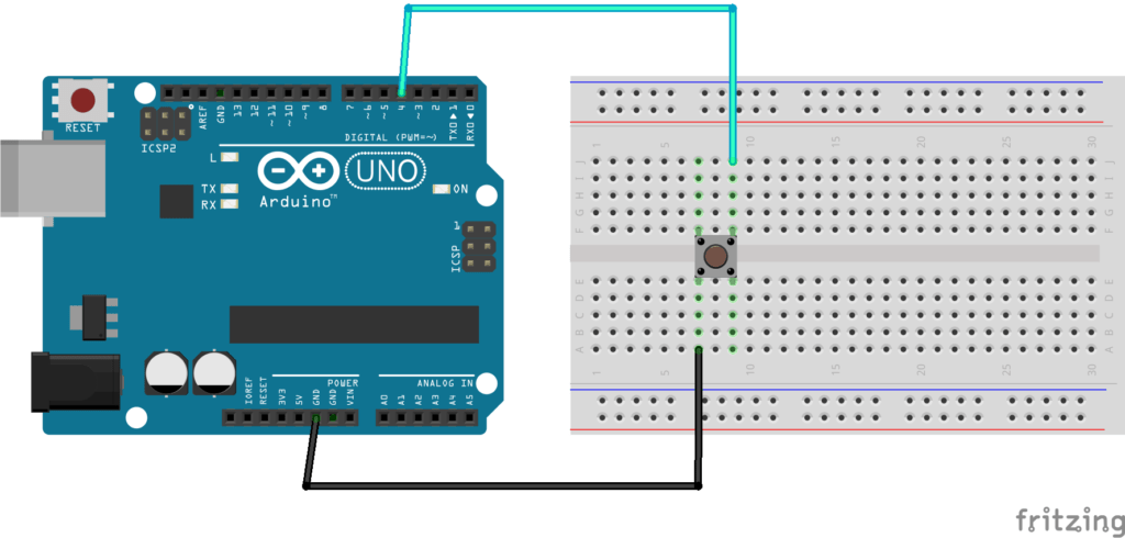
Here’s the circuit we’ll make.
You are learning how to use Arduino to build your own projects?
Check out Arduino For Beginners and learn step by step.
Steps to build the circuit:
- Make sure to power off the Arduino.
- Plug the push button in the middle of the breadboard, like on the picture.
- On one button’s leg, plug a wire (black if possible) to a GND pin on the Arduino board.
- The top left and bottom left legs of the button are connected together, and the top right and bottom right legs are connected together. If you have plugged the GND wire on the left side, then plug another wire on the right side, so they are not connected together. This other wire goes to a digital pin, for example 4.
As for now there is no resistor involved in the circuit. In the following of this post we’ll talk more about this. Also, if you want to know more about Arduino pins, check out this Arduino Uno pinout guide.
Arduino code to read push button’s state
What we’re trying to do here is to simply read the state from the button and print it 10 times per second.
>> Watch this video as an additional resource to this tutorial section:
After watching the video, subscribe to the Robotics Back-End Youtube channel so you don’t miss the next tutorials!
Print the push button’s state
Here is the code to print the button’s state 10 times a second.
#define BUTTON_PIN 4

void setup()
{
  Serial.begin(9600);
  pinMode(BUTTON_PIN, INPUT_PULLUP);
}

void loop()
{
  Serial.println(digitalRead(BUTTON_PIN));
  delay(100);
}
Let’s break down this code line by line.
Code to setup the push button
#define BUTTON_PIN 4
First we create a #define for the button pin, so we don’t need to write “4” every time we want to use this pin in our code. This will make your life easier, especially if you want to plug the button to another pin later on. This way you just need to modify one line of the code, which is at the top of the program – and thus easy to find.
void setup()
{
  Serial.begin(9600);
The void setup() function will be called first, only once. What we do here is to initialize Serial communication, so that we can use the Serial Monitor to print the data we got from the button.
  pinMode(BUTTON_PIN, INPUT_PULLUP);
}
This is how you initialize the push button in your code. In the void setup(), you use the pinMode() function with 2 arguments: first the button’s pin – here BUTTON_PIN will be replaced by “4” – and then the mode we want for the pin.
As we are going to read data from the button – not write – we choose an input mode. And then we still have 2 options: INPUT or INPUT_PULLUP. As we don’t have any resistor in our circuit, we will use INPUT_PULLUP to use the internal pull up resistor of the Arduino board. Note that in this tutorial I’m not going to dive deep into the explanation of INPUT_PULLUP, but if you want to know more, checkout this Arduino INPUT_PULLUP tutorial.
Code to read the push button’s state
void loop()
{
  Serial.println(digitalRead(BUTTON_PIN));
Now the pin for the button is initialized as input, and we enter the void loop(), which will be called again and again an infinite number of times.
To read the button’s state, we use the digitalRead() function, with one argument: the button’s pin. The result of that function is going to be either HIGH or LOW. Here, because we are in a pull up configuration (with INPUT_PULLUP), when the button is not pressed you will read HIGH. When the button is pressed you will read LOW.
Then, we put the result of digitalRead() into the function Serial.println(), which will simply print the data on the Serial Monitor.
  delay(100);
}
Just after reading the button’s state and printing it, we add a delay() of 100 milliseconds, which means that we’re going to do this action roughly 10 times per second. After we exit the void loop(), it is called again, etc etc.
Now you can test the code by compiling it and uploading it to your Arduino.
Open the Serial Monitor, and press/release the push button several times.
You will see something like this:
1
1
1
1
0
0
0
0
1
1
1
1
Every 100 milliseconds you will have a new line, with either 0 or 1.
As I previously wrote, the value you get out of digitalRead() is HIGH or LOW, but when you send it through Serial, this is going to be converted to 1 (HIGH) or 0 (LOW).
So, when the button is not pressed you will see “1” printed, and when the button is pressed, you will see “0”.
Improvement: Print a more explicit message
This first code is great as a minimal example to see the data coming from the push button. But in a real application, you may want to do more interesting things than just printing the button’s state. For example, you could read the button’s state, keep it inside a variable, and then depending on the value, do a specific action.
Let’s use the following Arduino code.
#define BUTTON_PIN 4

void setup()
{
  Serial.begin(9600);
  pinMode(BUTTON_PIN, INPUT_PULLUP);
}

void loop()
{
  byte buttonState = digitalRead(BUTTON_PIN);

  if (buttonState == LOW) {
  	Serial.println("Button is pressed");
  }
  else {
  	Serial.println("Button is not pressed");
  }
  delay(100);
}
The setup phase is the same. And as you can see in the loop(), now we store the value we got from digitalRead() into a variable, that we name buttonState. The data type for this variable is byte, which is what you need for the values HIGH and LOW.
Then, with a simple if structure, we check if the state is LOW, which means that, in our configuration with the internal Arduino pull up resistor, the button is pressed. When we detect this, we can decide to do any action we want. And if the condition is false, which means that the state is HIGH (because there are just 2 possible states), we know that the button is not pressed.
Now you can run this code, and see “Button is not pressed” printed every 100 milliseconds, and when you press on the push button, “Button is pressed”.
Button is not pressed
Button is not pressed
Button is not pressed
Button is not pressed
Button is pressed
Button is pressed
Button is pressed
Button is not pressed
Button is not pressed
This is a nice improvement to the previous code, which gives us more context and allows the code to grow with more functionalities.
Using pull up/down resistors
For now we haven’t used any resistor in our circuit – actually we did but this is the internal Arduino resistor.
Basically, when you plug a push button to a digital pin, the value the Arduino reads is between 0V and 5V. If the value is close to 0V, you will get LOW in your code, and if it’s close to 5V, you will get the value HIGH.
If you don’t put any resistor, the value may be “floating” between 0V and 5V, hence giving you random and weird results. By adding a resistor, you can force the default state to be either LOW or HIGH. And when you press on the button the state will become the opposite.
So we have 3 options here:
- No resistor, but use the INPUT_PULLUP mode to activate the internal pull-up resistor (will force default reading voltage to 5V – HIGH).
- Add a pull-up resistor (default value: HIGH).
- Add a pull-down resistor (default value: LOW).
For more details about pull up/down resistors, read this INPUT_PULLUP tutorial.
So, we already have used the option 1, now let’s see how to work with option 2 and 3.
And why should we actually consider options 2 and 3, if we can just build the circuit without any resistor? Well, because the internal pull up resistor is quite weak compared to what we’re going to add manually in the circuit. This might lead to unreliable results, if you have longer wires for example.
Arduino push button with external pull up resistor
For this circuit you will need a 10k Ohm resistor, and every other component we previously used.

- Before you modify the circuit make sure to power off the Arduino, to avoid any risk for your hardware.
- For the ground wire (black) and data wire (blue), that’s the same thing as before. Make sure they are on different sides of the button – for example GND on left side, and digital pin on right side.
- You are going to add the 10kOhm resistor to the same side as the digital pin connection – in this example on the right side. The other leg of the resistor goes to a different line on the breadboard, and from this leg, you add a wire (red) to the 5V pin of the Arduino. This is the pull up resistor, which will make sure the default voltage you read is 5V, hence HIGH in the code.
Now, here’s the code.
#define BUTTON_PIN 4

void setup()
{
  Serial.begin(9600);
  pinMode(BUTTON_PIN, INPUT);
}

void loop()
{
  byte buttonState = digitalRead(BUTTON_PIN);

  if (buttonState == LOW) {
  	Serial.println("Button is pressed");
  }
  else {
  	Serial.println("Button is not pressed");
  }
  delay(100);
}
As you can see, the code is the same, we just modified the mode in the pinMode() function. Instead of using INPUT_PULLUP, which will set the pin as INPUT + activate the internal pull up resistor, we just use INPUT.
Arduino push button with external pull down resistor
For this circuit we will also use a 10k Ohm resistor.
The principle is the same, but note that things are a bit different here:
- Once again, make sure to power off the Arduino before doing anything.
- You are going to add the 10k Ohm resistor on the side connected to the ground. So, starting from one leg of the button, you have the resistor, and then a wire (black) connected to GND.
- The wire connected to the digital pin should now be on the same side as the resistor – in this example, both GND and digital pin connections are on the left side (and not on opposite sides).
- You add a wire (red) between one leg of the button – from the opposite side of GND, so here on the right side – and 5V.
And here is the code.
#define BUTTON_PIN 4

void setup()
{
  Serial.begin(9600);
  pinMode(BUTTON_PIN, INPUT);
}

void loop()
{
  byte buttonState = digitalRead(BUTTON_PIN);

  if (buttonState == HIGH) {
  	Serial.println("Button is pressed");
  }
  else {
  	Serial.println("Button is not pressed");
  }
  delay(100);
}
As you can see, we also use the INPUT mode in the pinMode() function.
But now, when we read the state from the push button, LOW means that the button is not pressed. So we have to change the way we analyze the data in our code. That’s what you can see on line 13: if the state is HIGH, now it means the button has been pressed.
Detect a change of state
Great, you can now read the button’s state, and do something different in your code, if the button is pressed or not.
But what if you want to detect not the state itself, but a change of state? For example, when the button’s state goes from “not pressed” to “pressed” (press), or the opposite (release). Depending on your application that can be super useful.
And for that we can use 2 methods: interrupts and polling.
For those 2 methods I’m going to give you a fair introduction here – code that will get you started with a basic understanding – but if you want to know more, I’ve put some links to other in-depth tutorials in the conclusion section of this tutorial.
Use interrupts with the push button
With interrupts you can basically create a function that is going to be called when a certain change happens in a digital pin. The call of this function will “interrupt” the normal flow of the program.
Only certain digital pins can be used for interrupts. On Arduino Uno, you can use pin 2 and 3. As the button is currently connected to pin 4, we need to modify the circuit.
Here is the circuit with the external pull-down resistor, but this time the data wire is connected to digital pin 3.
Now, the code to detect when the button is released:
#define BUTTON_PIN 3

volatile byte buttonReleased = false;

void buttonReleasedInterrupt() {
  buttonReleased = true;
}

void setup() {
  Serial.begin(9600);
  pinMode(BUTTON_PIN, INPUT);
  attachInterrupt(digitalPinToInterrupt(BUTTON_PIN),
                  buttonReleasedInterrupt,
                  FALLING);
}

void loop() {
  if (buttonReleased) {
    buttonReleased = false;
    // do something here, for example print on Serial
    Serial.println("Button released");
  }
}
The way to initialize the button is the same as before.
We then create a new function called buttonReleasedInterrupt(). This function will be called when the interrupt is triggered – with FALLING mode, which means button’s state going from HIGH to LOW.
So, when the button is released (state goes from HIGH to LOW), the function is called. We set a boolean value (marked as “volatile”, because we modify it inside an interrupt) to true, and in the void loop(), we check for that boolean. If it’s true, then we know the button has been released. We set the boolean back to false and do any action we want, for example we can print “Button released” on the Serial Monitor.
Important note: don’t use Serial directly inside an interrupt function.
If you want more a detailed explanation, I’ve also written a complete tutorial on Arduino interrupts, which will also give you all the dos/don’t for using interrupts correctly.
Detect change of state with polling
Let’s try another way to check if the button has been released, by continuously polling the state.
#define BUTTON_PIN 3

byte lastButtonState = LOW;

void setup() {
  Serial.begin(9600);
  pinMode(BUTTON_PIN, INPUT);
}

void loop() {
  byte buttonState = digitalRead(BUTTON_PIN);
  if (buttonState != lastButtonState) {
    lastButtonState = buttonState;
    if (buttonState == LOW) {
      // do an action, for example print on Serial
      Serial.println("Button released");
    }
  }
}
Again, we initialize the button the same way we did before.
We also keep a global variable named lastButtonState, so we can compare the current button’s state we read with the previous one.
In the void loop(), we constantly check on the button’s state. If the state is different than the previous one, it means something happened: either we have just pressed on the button, or just released. In both cases we save the current state as the last state.
And then we check if the state is LOW. If yes – in our pull down resistor configuration – it means that we have released the button. If you were using the pull up configuration, you’d have to do the opposite: check if the state is HIGH.
Debounce the button
The problem with the code above is that when you run it, on some occasions you might see multiple “Button released” when you just release the button once.
This is because the button is physically “bouncing” when you touch it (going from LOW to HIGH and HIGH to LOW many times in a short interval), just like when you drop a ball on the floor. The ball doesn’t just reach the floor and stays here, it will bounce a few times before stabilizing. This is similar for the push button.
Fortunately we can solve this in our code.
#define BUTTON_PIN 3

byte lastButtonState = LOW;

unsigned long debounceDuration = 50; // millis
unsigned long lastTimeButtonStateChanged = 0;

void setup() {
  Serial.begin(9600);
  pinMode(BUTTON_PIN, INPUT);
}

void loop() {
  if (millis() - lastTimeButtonStateChanged > debounceDuration) {
      byte buttonState = digitalRead(BUTTON_PIN);
      if (buttonState != lastButtonState) {
      lastTimeButtonStateChanged = millis();
      lastButtonState = buttonState;
      if (buttonState == LOW) {
        // do an action, for example print on Serial
        Serial.println("Button released");
      }
    }
  }
}
What we do here is basically to ignore any result from the push button for a given amount of time after the state has changed. This way, we can avoid reading the state when the button is physically bouncing.
To do this, before reading the button’s state, we check if the duration since the last time the state has changed is greater than the debounceDuration we’ve set – here 50 milliseconds. If yes, we read the button’s state. And then if we find that the state is different from the last one, we reset the lastTimeButtonStateChanged variable to the current time with millis(). By doing this, we will need to wait again the next time – at least 50 milliseconds.
For a more in-depth explanation of the debounce mechanism, watch this video:
Conclusion – Arduino Push Button
In this Arduino push button tutorial you’ve learnt how to:
- Properly create a circuit with a push button connected to your Arduino board,
- Read the button’s state,
- Use this state or change of state for various use cases.
To go further, I encourage you to check this tutorial on how to turn an LED on and off with a push button. In the tutorial you will see how to include the push button in various simple applications using LEDs. You will also get a much more complete explanation on the debounce mechanism.