So, you’ve been playing with your Raspberry Pi and the GPIO panel, and you’ve noticed that when you read the GPIOs, some of them give you the value HIGH (or 1) by default, some of them give you the value LOW (0). Why is that?
In this tutorial I will show you what is the default state for each GPIO on the Raspberry Pi, why it’s like this, and also what you can do if you want to “override” that default state.
To control the GPIOs we will use the RPi.GPIO Python module.
What you’ll see here applies for Raspberry Pi 4, but also for Raspberry Pi 3 and 2 (using the 40 GPIOs panel).
>> Here is a video version of this tutorial, as an additional resource:
You are learning how to use Raspberry Pi to build your own projects?
Check out Raspberry Pi For Beginners and learn step by step.
After watching the video, subscribe to the Robotics Back-End Youtube channel so you don’t miss the next tutorials!
Table of Contents
GPIOs default state for Raspberry Pi
The concerned GPIOs
For this tutorial I will use the Raspberry Pi’s pins whose primary function is the “standard GPIO” function.
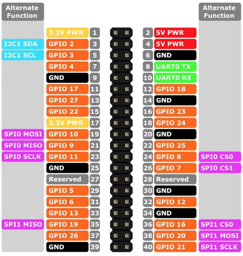
Basically I’m talking about the pins you can see in orange in the previous image, with a GPIO number. We will use this GPIO number and not the pin number (white text on grey background). For example, GPIO 26 and not pin 37. If you want a complete overview, check out this Raspberry Pi pin-out guide.
When the default states apply
First, let’s define exactly what is the “default state”. The default state for GPIO applies with the following conditions. You’ve:
- Boot the Raspberry Pi.
- Set a GPIO as input.
- Read the GPIO’s state.
And you’ve not:
- Added any external pull up/down resistor.
- Used the GPIO.cleanup() before.
- Configured the pin as output before setting it as input.
If you’ve done any of the previous things, you’ll have to reboot your Pi in order to get the default states again.
Default states for Raspberry Pi’s GPIOs
So, provided that you’ve followed the 3 steps and not done any of the “don’t do” steps, you will see the following:
- GPIOs up to 8: default state is 1 (HIGH, or close to 3.3V).
- GPIOs 9 to 27: default state is 0 (LOW, or close to 0V).
Code to test GPIO default states
Here’s a Python code you can run on your Raspberry Pi to test yourself. If you don’t know how to run a Python script on your Pi, check out this intro to Thonny IDE (for Raspberry Pi OS), or how to run a Python program in the terminal.
import RPi.GPIO as GPIO

GPIO.setmode(GPIO.BCM)

GPIOs = [2, 3, 4, 5, 6, 7, 8, 9, 10, 11,
         12, 13, 16, 17, 18, 19, 20, 21,
         22, 23, 24, 25, 26, 27]

# Setup all GPIOs to input
for gpio in GPIOs:
    GPIO.setup(gpio, GPIO.IN)

# Read state for each GPIO
for gpio in GPIOs:
    print("GPIO no " + str(gpio) + ": " + str(GPIO.input(gpio)))

# Cleanup all GPIOs - state will be different after that!
GPIO.cleanup()
In this code you can see an array containing all the GPIOs we are using (from the previous pins image).
Then, we set the mode for each GPIO to input – GPIO.IN, and we read the state for the GPIO with GPIO.input(gpio). We print that state along with the GPIO number.
So, the first time we run this program, we get:
GPIO no 2: 1
GPIO no 3: 1
GPIO no 4: 1
GPIO no 5: 1
GPIO no 6: 1
GPIO no 7: 1
GPIO no 8: 1
GPIO no 9: 0
GPIO no 10: 0
GPIO no 11: 0
GPIO no 12: 0
GPIO no 13: 0
GPIO no 16: 0
GPIO no 17: 0
GPIO no 18: 0
GPIO no 19: 0
GPIO no 20: 0
GPIO no 21: 0
GPIO no 22: 0
GPIO no 23: 0
GPIO no 24: 0
GPIO no 25: 0
GPIO no 26: 0
GPIO no 27: 0
As you can see, GPIOs up to 8 get the state 1 (HIGH, or close to 3.3V), and GPIOs from 9 to 27 get the state 0 (LOW, or close to 0V).
And then, one thing we do at the end of the program is to call the GPIO.cleanup() function. This function will reset the mode of all pins to input, to avoid letting some pins as output, which can be dangerous for the Pi. And – warning! – this will also alter the future state (which will not be “default” anymore) of the GPIOs in input mode.
So, if you run this program a second time, you will get:
GPIO no 2: 1
GPIO no 3: 1
GPIO no 4: 1
GPIO no 5: 1
GPIO no 6: 1
GPIO no 7: 1
GPIO no 8: 1
GPIO no 9: 1
GPIO no 10: 1
GPIO no 11: 1
GPIO no 12: 1
GPIO no 13: 1
GPIO no 16: 1
GPIO no 17: 1
GPIO no 18: 1
GPIO no 19: 1
GPIO no 20: 1
GPIO no 21: 1
GPIO no 22: 1
GPIO no 23: 1
GPIO no 24: 1
GPIO no 25: 1
GPIO no 26: 1
GPIO no 27: 1
This is because the function GPIO.cleanup() was executed during the first program run. Now if you want to get the default states again, you’ll have to reboot your Pi. Also note that if you only plan to use GPIOs as input, you don’t need to call GPIO.cleanup(). This function is only useful when you have GPIOs set as output mode.
Another thing: if you have set your GPIOs to output mode, and then to input, chances are that you’re going to read 1 (HIGH) for all GPIOs.
As you can see, the default state is only after you boot your Pi, under a certain set of circumstances. Then, it’s quite probable that this “default” state will be modified in your future programs.
Why is the GPIO default state like that?
First, on page 102 of the Broadcom 2835 datasheet (Broadcom 2835 is the more technical name for the GPIO header), check the second column named “Pull”. In this column, for each GPIO, you will see either HIGH or LOW.
This value is also the same you found when running the code: HIGH for GPIOs up to 8, and LOW for GPIOs starting from 9.
Here, HIGH means that there is a default pull up resistor on the pin, and LOW means there is a default pull down resistor on the pin. I’m not going to explain everything about pull up and down resistors, just this:
- When you add a resistor between a component and the ground, this is a pull down resistor, which will make sure the default voltage you read is close to 0V.
- When you add a resistor between a component and Vcc (power supply), this is a pull up resistor, which will make sure the default voltage you read is close to Vcc (3.3V for the Raspberry Pi)
So, what this tells you is that for GPIOs 0 to 8, there is an internal pull up resistor, which will make you read 1 (HIGH) by default. For GPIOs 9+, there is an internal pull down resistor, which will make you read 0 (LOW) by default.
Now, what is the value of this pull up/down resistor?
Unfortunately, it’s not possible to know exactly. The actual Raspberry Pi hardware is not open source (most of the software is, not the hardware), so there is no way to know directly from the Raspberry Pi Foundation. However, with some tests published by users on the Internet, we can approximate this internal resistor to be 50kOhm.
How to “override” the default state for Raspberry Pi’s GPIOs
Now let’s have a look at 2 different ways you can override this default state for the GPIOs. You may be fine with the default state, but you could also want to set the default state to something else (all HIGH, all LOW, or a mix of both).
Override the default state with the code
Using the RPi.GPIO Python module, you can choose to make the internal resistor as a pull up, or a pull down resistor, for any given GPIO.
Here’s a code example with just one GPIO.
import RPi.GPIO as GPIO

GPIO.setmode(GPIO.BCM)

gpio_number = 8

GPIO.setup(gpio_number, GPIO.IN, pull_up_down=GPIO.PUD_UP)

print("GPIO no " + str(gpio_number) + ": " + str(GPIO.input(gpio_number)))
To choose what is going to be the internal resistor, you have to add the option “pull_up_down=” to the GPIO.setup() function, with:
- GPIO.PUD_UP for pull up.
- GPIO.PUD_DOWN for pull down.
If you run this code (using GPIO.PUD_UP), you’ll get the result: GPIO no 8: 1.
And if you change the code (using GPIO.PUD_DOWN instead of GPIO.PUD_UP), you’ll get: GPIO no 8: 0.
This way, with just one small addition in your code, you can decide yourself of the default state for any GPIO.
Override the default state with an external pull up/down resistor
This method requires you to add a resistor to your circuit, for each GPIO you want to use. So basically you’ll have both the internal pull up/down resistor, and your own external pull up/down resistor. To make your external resistor “take over”, you just have to provide a stronger value, for example 10kOhm. 10kOhm is stronger than 50kOhm, it works in reverse for the resistors.
Here is an example with a circuit containing a push button and an LED.

For the LED, you have a resistor, but this is different. The GPIO for the LED will be configured as output, and the resistor is here simply to limit the current that goes through the LED. As we’ve seen before, the default state issue is only when you read a GPIO in input mode.
For the push button, you can see a 10kOhm resistor between one leg (same side as the connection with a GPIO), and the ground (GND). This pull down resistor will make sure that when you read the value from the push button, you will get 0 (LOW) when the push button is not pressed, and 1 (HIGH) when the button is pressed.
With this external pull down resistor, you are sure to get the same value every time. The internal pull up/down resistor is too weak compared to this external resistor, it won’t have any effect. So, in this case using the option pull_up_down=GPIO.PUD_UP or GPIO.PUD_DOWN will have no effect.
Conclusion – Raspberry Pi’s GPIOs default state – What to do
As you’ve seen in this tutorial, each GPIO on the Raspberry Pi has a 50kOhm internal resistor, which can be used as a pull up or pull down resistor in your code.
And by default, before you set anything, the resistors for GPIOs up to number 8 will automatically be set as pull up, and for GPIOs after number 9, pull down.
This default state will only be activated after you boot the Pi. If you use the GPIOs in your code you might change that “default” state for any other program you run after that. The only way to come back to the “true” default state is by rebooting your Raspberry Pi.
So, a recommendation here is to choose yourself (or “override”) the default state when you use a GPIO as input. You don’t want to get values that are hard to predict.
The first option is to set the internal pull up/down resistor in your code, for example with the RPi.GPIO module. But this option is not optimal. The value of the resistor – 50kOhm – is quite weak actually, and if you have longer wires, you might experience weird behaviors.
The best option is to add an external 10kOhm resistor by yourself, either in pull up (connected to Vcc) or pull down mode (connected to ground). This is a bit more work, but with this you will be sure to get predictable and stable results when you read data from a component.