[NOTE] The WiringPi library is not supported anymore by its initial author, however there is a fork on GitHub where the open source community is continuing to provide support updates. I am leaving this tutorial as it was first published, because it might still be useful, but be aware that some information might not be correct. [/NOTE]
In this tutorial I’ll show you how to communicate between a Raspberry Pi 4 (also works with 3, 3B, 3B+) and an Arduino (Uno), using the I2C protocol.
The Raspberry Pi will be configured as a master, and the Arduino as a slave.
You’ll see how to setup the communication, read an write, thanks to the WiringPi library. I’ll also show you the differences between using WiringPi for a typical sensor and an Arduino board.
Make sure to read this introduction to WiringPi before if you don’t know the library well.
Table of Contents
Setup
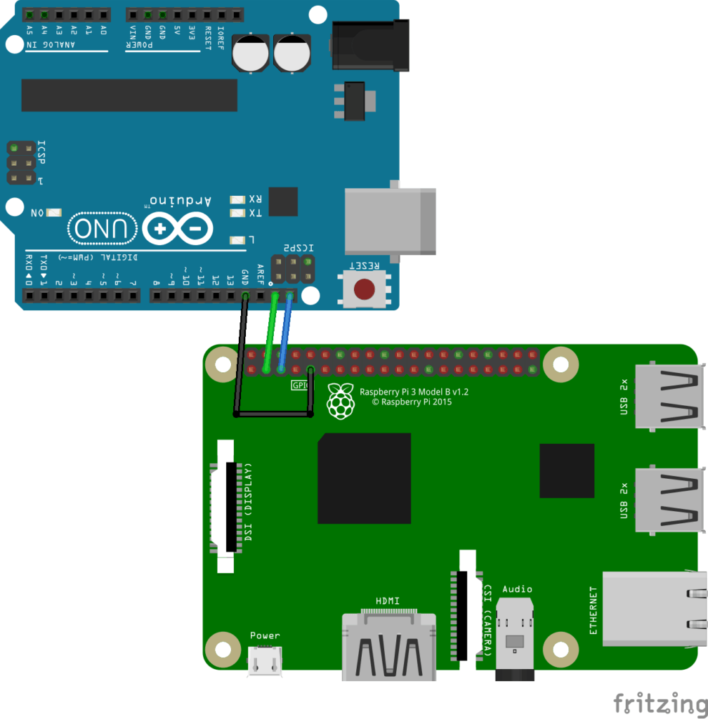
Hardware schematics
You are learning how to use the combo Raspberry Pi + Arduino to build your own projects?
Check out Raspberry Pi and Arduino and learn step by step.
- Link the GND of the Raspberry Pi to the GND of the Arduino.
- Connect the SDA (I2C data) of the Pi (pin 2) to the Arduino SDA.
- Connect the SCL (I2C clock) of the Pi (pin 3) to the Arduino SCL.
Important note: the Raspberry Pi 4 (and earlier) is running under 3.3V, and the Arduino Uno is running under 5V!
You should really pay attention when you connect 2 pins between those boards. Usually you’d have to use a level converter between 3.3V and 5V. But in this specific case we can avoid using one.
If the Raspberry Pi is configured as a master and the Arduino as a slave on the I2C bus, then you can connect the SDA and SCL pins directly. To make it simple, in this scenario the Raspberry Pi will impose 3.3V, which is not a problem for the Arduino pins.
To learn more about gpio headers: Raspberry Pi pinout guide | Arduino Uno pinout guide.
Software setup
If you haven’t used I2C on your Raspberry Pi yet, it probably means that the I2C communication is not activated. To activate it, search for the “/boot/config.txt” file.
Open this file (with sudo), find the line #dtparam=i2c_arm=on, and remove the leading ‘#’ to uncomment it.
After that, reboot your Pi, and I2C will be activated as long as you don’t comment the I2C line again in the config file.
Basic Arduino I2C slave program
Let’s write the most basic program to use Arduino as an I2C slave.
#include <Wire.h>

#define SLAVE_ADDRESS 0x08

byte data_to_echo = 0;

void setup()
{
  Wire.begin(SLAVE_ADDRESS);

  Wire.onReceive(receiveData);
  Wire.onRequest(sendData);
}

void loop() { }

void receiveData(int bytecount)
{
  for (int i = 0; i < bytecount; i++) {
    data_to_echo = Wire.read();
  }
}

void sendData()
{
  Wire.write(data_to_echo);
}
Upload this code to your Arduino board. The Arduino is now configured as an I2C slave and its device ID is 8.
When receiving a byte through I2C, the Arduino will keep the data in a global variable, and send it back when asked to send a byte.
Raspberry Pi I2C master program with WiringPi
Make sure the Raspberry Pi detects the Arduino board on the I2C bus
After you’ve setup the hardware, software, and uploaded the Arduino code, it’s time to focus on the Raspberry Pi part and write the WiringPi program!
But before that, let’s just check that the Raspberry Pi can detect the Arduino board on the I2C bus.
$ i2cdetect -y 1
     0  1  2  3  4  5  6  7  8  9  a  b  c  d  e  f
00:          -- -- -- -- -- 08 -- -- -- -- -- -- --
10: -- -- -- -- -- -- -- -- -- -- -- -- -- -- -- --
20: -- -- -- -- -- -- -- -- -- -- -- -- -- -- -- --
30: -- -- -- -- -- -- -- -- -- -- -- -- -- -- -- --
40: -- -- -- -- -- -- -- -- -- -- -- -- -- -- -- --
50: -- -- -- -- -- -- -- -- -- -- -- -- -- -- -- --
60: -- -- -- -- -- -- -- -- -- -- -- -- -- -- -- --
70: -- -- -- -- -- -- -- --
Alright, let’s now write the code!
Raspberry Pi code with WiringPi I2C
#include <iostream>
#include <wiringPiI2C.h>

#define DEVICE_ID 0x08

int main (int argc, char **argv)
{
    // Setup I2C communication
    int fd = wiringPiI2CSetup(DEVICE_ID);
    if (fd == -1) {
        std::cout << "Failed to init I2C communication.\n";
        return -1;
    }
    std::cout << "I2C communication successfully setup.\n";

    // Send data to arduino
    uint8_t data_to_send = 17;
    wiringPiI2CWrite(fd, data_to_send);
    std::cout << "Sent data: " << (int)data_to_send << "\n";

    // Read data from arduino
    int received_data = wiringPiI2CRead(fd);
    std::cout << "Data received: " << received_data << "\n";

    if (received_data == data_to_send) {
        std::cout << "Success!\n";
    }
    return 0;
}
WiringPi Code explained
Let’s break down the code line by line.
Setup
#include <iostream>
#include <wiringPiI2C.h>
Here we include the WiringPiI2C header, which is part of the WiringPi library. You can find the complete header file on GitHub.
#define DEVICE_ID 0x08
On Arduino we chose to set the ID to 8. So here on Raspberry Pi we have to use the same ID to find the Arduino device on the I2C bus.
Note that it’s quite different from when you use I2C to read data from a sensor. When using a sensor, usually the ID is already set, and you have to find it in the datasheet. Here you can choose whatever ID you want.
Init I2C communication
int main (int argc, char **argv)
{
    // Setup I2C communication
    int fd = wiringPiI2CSetup(DEVICE_ID);
    if (fd == -1) {
        std::cout << "Failed to init I2C communication.\n";
        return -1;
    }
    std::cout << "I2C communication successfully setup.\n";
With the wiringPiI2CSetup(), your Raspberry Pi will try to detect and connect to your Arduino board. The parameter you have to give to the function is the device ID of the I2C slave on the bus.
After the communication is successfully established, we can start sending and receiving data.
Send data to Arduino via I2C
    // Send data to arduino
    uint8_t data_to_send = 17;
    wiringPiI2CWrite(fd, data_to_send);
    std::cout << "Sent data: " << (int)data_to_send << "\n";
To send a byte to Arduino, we use the wiringPiI2CWrite() function. Note that the data type I chose here is uint8_t, which corresponds to a 8-bit unsigned number (0-255).
There is a difference here from when you write data to a typical sensor. Usually with a sensor device you have to check the register table in the device datasheet. Then, when writing a byte through I2C, you have to give the device ID, the register address, and the data. In this case you’ll use the wiringPiI2CWriteReg8() and wiringPiI2CWriteReg16() WiringPi functions.
Here, with wiringPiI2CWrite() you don’t need to give any register address. You just put the device ID and the data to send. This will go directly into the callback function you’ve set on Arduino using Wire.onReceive().
Receive data from Arduino via I2C
    // Read data from arduino
    int received_data = wiringPiI2CRead(fd);
    std::cout << "Data received: " << received_data << "\n";
To receive a byte from Arduino, we use the wiringPiI2CRead() function.
This is also different from when you use a sensor, for which the data is set in different registers, with different addresses. With a typical sensor you would have used wiringPiI2CReadReg8() and wiringPiI2CReadReg16(), where you need to give the device ID and the register address.
Here, with wiringPiI2CRead(), all you need to give as a parameter is the device ID of the Arduino slave. The Arduino will trigger the callback for the function you set with Wire.onRequest().
    if (received_data == data_to_send) {
        std::cout << "Success!\n";
    }
    return 0;
}
Finally, we compare the sent and received data to see if there’s the same. On success, we print a message on the terminal.
Compile and run the program
Don’t forget to link to the wiringPi library by using -lwiringPi.
$ g++ -o rpi_arduino_wiringpi_i2c rpi_arduino_wiringpi_i2c.cpp -lwiringPi
$ ./rpi_arduino_wiringpi_i2c
I2C communication successfully setup.
Sent data: 17
Data received: 17
Success!
It works!
With only 3 WiringPi functions, you’ve setup the I2C communication, sent a byte, and received a byte.
To go further, you could add more Arduino boards to the I2C bus (by using a different device ID for each one), also configured as slaves. Your Raspberry Pi board, as a master on the bus, would have to setup the communication for each device. After that, everything is the same: you just need to change the device ID parameter in the WiringPi functions, depending on which slave device you’re talking to.
