[NOTE] The WiringPi library is not supported anymore by its initial author, however there is a fork on GitHub where the open source community is continuing to provide support updates. I am leaving this tutorial as it was first published, because it might still be useful, but be aware that some information might not be correct. [/NOTE]
WiringPi is a Cpp library for Raspberry Pi. With this library you can use many of the functionalities provided by the GPIO header: digital pins, SPI, I2C, UART, etc.
Although there are many Python libraries for Raspberry Pi GPIOs, Cpp is quite a bit behind. Fortunately, there is WiringPi.
In this post you’ll install WiringPi, get to know how to use it, and see many practical points which will be useful when you work with this library on your own projects.
After this overview and starting guide, you’ll find many other WiringPi tutorials:
- Read data from a sensor with I2C (ADXL345)
- Communicate between a Raspberry Pi (master) and an Arduino (slave) via I2C
- Communicate between a Raspberry Pi (master) and an Arduino (slave) via SPI
- Use and compile WiringPi with ROS
Table of Contents
Install WiringPi
This step will depend on the operating system you’ve installed on your Raspberry Pi.
You are learning how to use Raspberry Pi to build your own projects?
Check out Raspberry Pi For Beginners and learn step by step.
WiringPi on Raspberry Pi OS
If you’re running Raspberry Pi OS, WiringPi should already be installed!
You can find out easily:
$ gpio -v
gpio version: 2.46
Copyright (c) 2012-2018 Gordon Henderson
This is free software with ABSOLUTELY NO WARRANTY.
For details type: gpio -warranty

Raspberry Pi Details:
  Type: Pi 3+, Revision: 03, Memory: 1024MB, Maker: Sony
  * Device tree is enabled.
  *--> Raspberry Pi 3 Model B Plus Rev 1.3
  * This Raspberry Pi supports user-level GPIO access.
If you have a Raspberry Pi 4 board, the “Raspberry Pi Details” section will be a little bit different, but the functionalities of WiringPi remain the same.
Install WiringPi on Linux (general)
Raspbian is the officially supported OS for Raspberry Pi, but there are many other Linux OSes adapted for the Pi, for example Ubuntu Mate.
If you have a non-Raspbian OS you’ll need to install WiringPi from source, through the following steps.
$ sudo apt-get purge wiringpi
$ hash -r
$ git clone --branch final_official_2.50 https://github.com/WiringPi/WiringPi.git ~/wiringpi
$ cd ~/wiringPi
$ ./build
Executing those command lines will get the source code from git, fetch the latest update, and build WiringPi.
Once you’ve executed all the steps, check if WiringPi is correctly installed with gpio -v.
Upgrade for Raspberry Pi 4B
If you’re using Raspberry Pi 4B, the following gpio readall command might not work for you. You have to upgrade the library from version 2.50 to 2.52.
To do that, just run the following commands.
$ cd /tmp
$ wget https://project-downloads.drogon.net/wiringpi-latest.deb
$ sudo dpkg -i wiringpi-latest.deb
After the installation
Make sure WiringPi is correctly installed by running gpio -v.
Now, in order to use WiringPi in your Cpp code you need to know 2 things:
- In your Cpp programs, add the <wiringPi.h> header.
- When compiling, add
-lwiringPito the g++ parameters so it will find and link your program to the WiringPi library.
Check all pins on the Raspberry Pi with WiringPi
WiringPi is not only a Cpp library. It contains some useful command line utilities to help you see the state of your GPIOs and do some debugging.
Before diving into the code, let’s check what pins you can use.
Complete pin overview with gpio readall
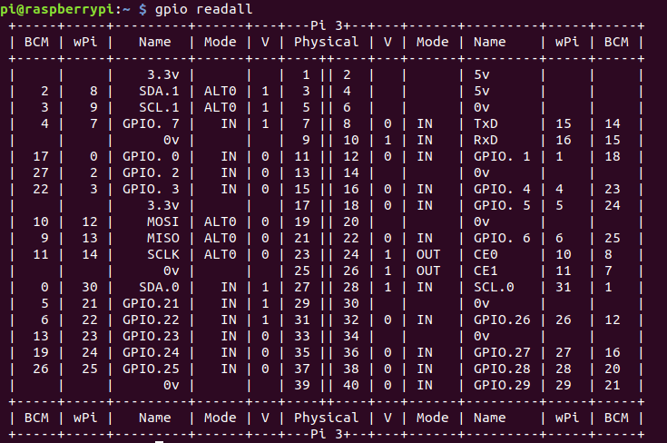
With gpio readall, you can get a complete overview of all available pins on your Pi board. We’ll also see later in this post how to use other functions of the WiringPi gpio command line tool.
Depending on the Pi you have (4, 3B+, 3B, …) you’ll get something like this:
And to compare, here is the Raspberry Pi pinout (for more info, here is a complete guide about Raspberry Pi 4, 3B, 3B+ pinout):

The table you see with gpio readall is quite complete, it gives you a lot of useful information. The table is separated into 2 parts, which are mirrored, exactly as the Raspberry Pi pinout overview on the second image.
gpio readall: what does each column mean?
Here are some explanations for each column from this table:
- Physical: it just matches the physical pins from the GPIO header, so you can localize the pins on your board.
- V: the current “value” of the pin, basically this columns says if the given pin is on a LOW or HIGH state.
- Mode: A pin needs to be set in a certain “mode” to perform operations. Most common modes for digital pins are INPUT (you can read value from the pin) and OUTPUT (you can write a value to the pin). You can also notice the mode ALT0, which is here used for the I2C protocol (SDA, SCL) and the SPI protocol (MOSI, MISO, SCLK).
- Name: If you look at the second image with the Raspberry Pi pinout, you can see that the “Name” column just displays the standard function of each pin, and if applicable, overrides this standard function by the alternate function. Note that the GPIO numbers corresponds to the “wPi” column and not the “BCM” column.
- wPi: the pin numbers actually used by the WiringPi library. This numbering convention was set quite a long time ago when the WiringPi library was first written. It ensures the pin numbers stay the same for all board revisions. But unless you use a very old board (< Raspberry Pi 2), there is no real point in using this convention anymore.
- BCM: The Raspberry Pi board has a BCM2835 (Broadcom SOC Channel). It defines pin numbers and alternate functions for the GPIO header. This numbering convention is now the most used among the Raspberry Pi community.
To recap, this table can help you get a quick overview of all pins, what number to use for each pin, and the current mode/state for a given pin.
As a general rule, prefer using the BCM numbering convention over the WiringPi convention. This will be easier for you to be in sync with other developers, and if you switch to another library (for example RPi.GPIO with Python), you will be able to use the same pin numbers.
A simple code example with WiringPi
In this example we’ll manage a LED and a push button using the Raspberry Pi GPIO header.
The goal of the program is to use WiringPi to read the data from the push button (digital input) and power the LED on (digital output) when the button is pressed.
We’ll use the core functions from the WiringPi library, and if you’re familiar with Arduino, you’ll see that those functions are almost the same!
The pin numbers inside WiringPi code follow the BCM pin numbering, so, use the “BCM” column from the previous table in order to find the correct number to use.
Hardware setup
The LED is connected to BCM pin 17, which is also WiringPi pin 0, and physical pin number 11.
The push button is connected to BCM pin 18, which is also WiringPi pin 1, and physical pin number 12.
Let’s keep things simple and use only the BCM pin number convention (GPIO 17 and GPIO 18) for the rest of this tutorial.
In this hardware setup I’ve used a 220Ohm resistor for the LED and a 10kOhm pull-down resistor for the push button. The Raspberry already has some pull-up and pull-down resistors, but you’re never too careful. Also, if you’re used to work with Arduino, the setup stays the same, you could just replace your Pi with your Arduino and you won’t have to modify anything.
A few important things to consider when using the Raspberry Pi GPIOs:
- Make sure you don’t short-circuit any of the pins, this can damage the pins, and may also damage the microprocessor itself.
- The Raspberry Pi operates at 3.3V. Make sure that all sensors and actuators you want to use support 3.3V. Sometimes you’ll have to use a voltage level converter. Also, many Arduino boards (including Uno, Mega) operate at 5V, so you really need to pay attention if you don’t want to burn your Raspberry Pi.
WiringPi program
#include <iostream>
#include <chrono>
#include <thread>
#include <wiringPi.h>

#define PIN_LED 17
#define PIN_BUTTON 18

int main (int argc, char **argv)
{
    wiringPiSetupGpio();

    pinMode(PIN_LED, OUTPUT);
    pinMode(PIN_BUTTON, INPUT);

    printf("LED and button pins have beens setup.\n");

    while (1)
    {
        if (digitalRead(PIN_BUTTON) == HIGH) {
            digitalWrite(PIN_LED, HIGH);
        }
        else {
            digitalWrite(PIN_LED, LOW);
        }

        std::this_thread::sleep_for(std::chrono::milliseconds(10));
    }
}
Let’s compile the Cpp code to create an executable – and don’t forget to link to the WiringPi library!
$ g++ -o led_button led_button.cpp -lwiringPi
Here’s the kind of error you’ll get if you don’t link to WiringPi:
$ g++ -o led_button led_button.cpp
/tmp/cccrNGcL.o: In function `main':
led_button.cpp:(.text+0x14): undefined reference to `wiringPiSetupGpio'
led_button.cpp:(.text+0x20): undefined reference to `pinMode'
led_button.cpp:(.text+0x2c): undefined reference to `pinMode'
led_button.cpp:(.text+0x3c): undefined reference to `digitalRead'
led_button.cpp:(.text+0x64): undefined reference to `digitalWrite'
led_button.cpp:(.text+0x74): undefined reference to `digitalWrite'
collect2: error: ld returned 1 exit status
Now let’s run the program:
$ ./led_button
LED and button pins have beens setup.
If your hardware setup was correctly made, then when you press the button, the LED will be powered on, and when you release the button the LED will be powered off.
Code explained step by step
Let’s know break down the code line by line.
#include <iostream>
#include <chrono>
#include <thread>
#include <wiringPi.h>
The first thing to do is to include the WiringPi library with the <wiringPi.h> header.
#define PIN_LED 17
#define PIN_BUTTON 18
Using #define to set pin numbers is a good practice, also often used when writing Arduino programs. You can set all your pins at the top of your program and then it becomes very easy to modify your code if you physically change a pin location.
So, here we use BCM pin 17 for the LED and BCM pin 18 for the button.
int main (int argc, char **argv)
{
    wiringPiSetupGpio();
All your programs using WiringPi need to call a setup function at the beginning. Here, as we are using basic GPIOs, you can just call the wiringPiSetupGPio() function. Make sure it’s always at the top of your program, and make sure you only call it once!
    pinMode(PIN_LED, OUTPUT);
    pinMode(PIN_BUTTON, INPUT);

    printf("LED and button pins have beens setup.\n");
If you’ve already programmed on Arduino, you should feel very familiar with those 2 lines. If not, well that’s quite simple: before using a pin, we need to setup its mode. We set the LED pin as an OUTPUT pin, so we’ll be able to send a value to it. And we set the button pin as an INPUT pin, because we want to read a value from it.
The WiringPi library contains some useful #defines, such as INPUT, OUTPUT, HIGH, LOW. Always prefer using them in your code, instead of just 0 and 1.
    while (1)
    {
        if (digitalRead(PIN_BUTTON) == HIGH) {
            digitalWrite(PIN_LED, HIGH);
        }
        else {
            digitalWrite(PIN_LED, LOW);
        }

        std::this_thread::sleep_for(std::chrono::milliseconds(10));
    }
}
This code is pretty straightforward. We read the value from the button with the digitalRead() function. This value is either HIGH or LOW (1 or 0).
When the button is pressed (HIGH), we power on the LED with the digitalWrite() function, using HIGH. When the button is not pressed (LOW), we power off the LED using digitalWrite(), but this time with LOW.
Finally, we make the program sleep for 10 milliseconds between each iteration of the loop, so we don’t use too much CPU.
The WiringPi gpio command line tool
The gpio command line tool is quite useful to test your GPIOs quickly, directly from the terminal, without having to: 1. Write a Cpp code, 2. Compile it, and 3. Launch it.
In fact, you’ve already saw 2 functions: gpio -v gives you the current WiringPi version and some info about your Pi, and gpio readall prints a complete overview of all the pins on the GPIO header.
Let’s see a few other basic functions here. Keep the hardware setup you’ve made with the previous code example, we’ll use it to check that the commands we write are correctly working!
For all functions, we’ll need to give the number of the pin we want to use. As you saw before in this post, there are 3 different numbers for each pin: physical, wiringPi, and BCM. When writing Cpp code, the numbering convention is the BCM one. But when using gpio on a terminal, the convention is the WiringPi one, which can become quite confusing.
Fortunately there is a flag you add to use the BCM convention: gpio -g .... That’s what I recommend you to do in order to keep things simple.
gpio mode
Use gpio mode to change the mode of a pin. Note: this is quite obvious but GND and power (3.3V, 5V) pins can’t be changed and used for anything else than GND and power supply.
To set the LED pin (GPIO 17) as an OUTPUT pin, use gpio -g mode 17 out. If you run gpio readall again, you’ll see that the pin mode has now changed.
To set the button pin (GPIO 18) as INPUT, use gpio -g mode 18 in. Basically this pin should already be in INPUT mode when you boot the Pi, but it’s always better to setup a pin before using it, as another program may have changed it just before.
gpio read
Use gpio read to read the state of a pin which has been set as INPUT. The printed result will be either 0 or 1 (LOW or HIGH).
Here, after you’ve set the pin mode for the button, just run the command.
$ gpio -g read 18
0
Now, press the button, and run the command again (while pressing).
$ gpio -g read 18
1
gpio write
Use gpio write to set the state of a pin which has been set as OUTPUT. For the state parameter, write 0 for LOW and 1 for HIGH.
After you’ve set the pin mode for the LED, power it on with gpio -g write 17 1, and power it of with gpio -g write 17 0.
Going further with WiringPi and Raspberry Pi
In this post you have discovered what is WiringPi and how to control your Raspberry Pi GPIO header with it.
You can now easily install the WiringPi library, find information about a given pin on the terminal, and write a complete Cpp code to control digital pins.
This is a great step you’ve made, but there is still a lot more to learn!
The best way to learn is to find yourself a personal project. Choose a project that involves using different kinds of basic and complex sensors, and why not communicating with an Arduino board through the GPIO header.
Here is a list of tutorials you can use to expand your knowledge and practice with WiringPi: