[NOTE] The WiringPi library is not supported anymore by its initial author, however there is a fork on GitHub where the open source community is continuing to provide support updates. I am leaving this tutorial as it was first published, because it might still be useful, but be aware that some information might not be correct. [/NOTE]
In this tutorial I’ll show you how to communicate between a Raspberry Pi 4 (also works with 3, 3B, 3B+) and an Arduino (Uno), using the SPI protocol.
The Raspberry Pi will be configured as a master, and the Arduino as a slave. On Raspberry Pi we’ll use the WiringPi library inside a Cpp code example. More specifically we’ll use the WiringPiSPI sub-part of the library.
The goal of this tutorial is to send a byte from the Raspberry Pi to the Arduino, process this byte, and receive the new value on the Raspberry Pi.
Make sure to read this introduction to WiringPi before if you don’t know the library well.
Table of Contents
Setup
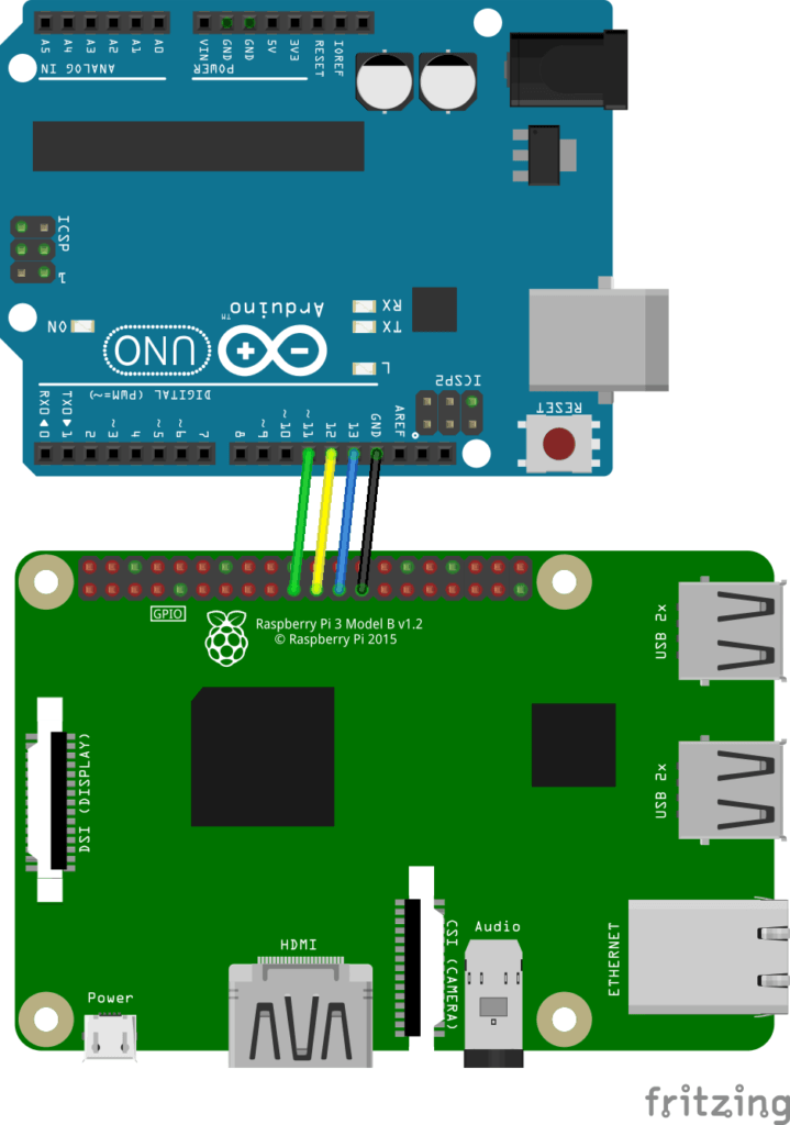
Hardware setup
You are learning how to use the combo Raspberry Pi + Arduino to build your own projects?
Check out Raspberry Pi and Arduino and learn step by step.
Connect those pins together:
- GND (first)
- MISO: Master In Slave Out
- MOSI: Master Out Slave In
- CLK: The clock
Make sure to connect MISO to MISO and MOSI to MOSI, not MISO to MOSI. The software side will handle that depending on which device is set as a slave or master.
Note that for SPI, you normally have another wire connected to CS (Chip Select), or SS (Slave Select). This is useful to choose which slave you are talking to. Here, as we have only one Arduino slave, no need for this wire, the communication will still work.
Also, something to really pay attention to: the Raspberry Pi operates at 3.3V, while the Arduino Uno operates as 5V. For this small example this is OK because the Raspberry Pi will impose its voltage. But if you decide to do anything more complex than that, I strongly recommend that you use a level converter (3.3V – 5V) to avoid burning some GPIOs.
To learn more about gpio headers: Raspberry Pi pinout guide | Arduino Uno pinout guide.
Software setup
If you haven’t used SPI on your Raspberry Pi yet, it probably means that the SPI communication is not activated. To activate it, search for the “/boot/config.txt” file.
Open this file (with sudo), find the line #dtparam=spi=on, and remove the leading ‘#’ to uncomment it.
After that, reboot your Pi, and SPI will be activated as long as you don’t comment the SPI line again in the config file.
Basic Arduino SPI slave program
Let’s write a basic Arduino code that setups the board as an SPI slave, and process data received over the SPI bus.
#include <SPI.h>

void setup() {
  // have to send on master in, *slave out*
  pinMode(MISO, OUTPUT);

  // turn on SPI in slave mode
  SPCR |= _BV(SPE);

  // turn on interrupts
  SPI.attachInterrupt();
}

// SPI interrupt routine
ISR (SPI_STC_vect)
{
  byte c = SPDR;

  SPDR = c+10;
}  // end of interrupt service routine (ISR) for SPI

void loop () { }
Upload this code to your board, your Arduino is now a slave on the SPI bus.
When a byte is received over SPI, the Arduino will read it from SPDR. After processing it (here: adding 10), the Arduino will set the SPDR register with the new value, so the master can read it on the next SPI transfer.
Raspberry Pi SPI master program with WiringPi
#include <iostream>
#include <wiringPiSPI.h>

#define SPI_CHANNEL 0
#define SPI_CLOCK_SPEED 1000000

int main(int argc, char **argv)
{
    int fd = wiringPiSPISetupMode(SPI_CHANNEL, SPI_CLOCK_SPEED, 0);
    if (fd == -1) {
        std::cout << "Failed to init SPI communication.\n";
        return -1;
    }
    std::cout << "SPI communication successfully setup.\n";

    unsigned char buf[2] = { 23, 0 };
    wiringPiSPIDataRW(SPI_CHANNEL, buf, 2);

    std::cout << "Data returned: " << +buf[1] << "\n";
    return 0;
}
WiringPi SPI Code explained
Let’s break down the code line by line.
Setup
#include <iostream>
#include <wiringPiSPI.h>
First we include the WiringPiSPI header, which is part of the WiringPi library. You can find the complete code for the header here on GitHub.
#define SPI_CHANNEL 0
#define SPI_CLOCK_SPEED 1000000
We set the SPI channel to 0. For the SPI clock speed we use 1 MHz. With WiringPi and Raspberry Pi you can choose a clock speed between 500 kHz and 32 MHz.
Init SPI communication
int main(int argc, char **argv)
{
    int fd = wiringPiSPISetupMode(SPI_CHANNEL, SPI_CLOCK_SPEED, 0);
    if (fd == -1) {
        std::cout << "Failed to init SPI communication.\n";
        return -1;
    }
    std::cout << "SPI communication successfully setup.\n";
First you have to know that there are different SPI modes: 0, 1, 2 and 3 – basically this is about polarity and phase of signals. But all you need to know to get started is: if you have a slave using mode 2, then your master needs to configure SPI with mode 2, so they can be “synchronized”. Here we are using mode 0, which is the default mode on Arduino.
Back to the code: you can setup an SPI communication with the wiringPiSPISetup() function, for which you have to give the SPI channel you’re using, and the clock speed you’ve chosen. Default SPI mode for this function is 0.
Note here that I used wiringPiSPISetupMode() instead. This function has one more parameter: the SPI mode. Apart from choosing the mode, it does the exact same thing as wiringPiSPISetup(). The only reason why I used this function here is to show you about the different SPI modes you can use.
The returned value for this function is a file descriptor. On success, we can start sending and receiving data over SPI!
Transfer data over SPI with Arduino
    unsigned char buf[2] = { 23, 0 };
    wiringPiSPIDataRW(SPI_CHANNEL, buf, 2);

    std::cout << "Data returned: " << +buf[1] << "\n";
    return 0;
}
The SPI protocol is quite special. You don’t just send values and then receive other values. With SPI each single communication is a transfer. You send a byte, and while you do that, you receive another one.
The wiringPiSPIDataRW() function allows you to transfer data over SPI. That’s the only function you’ll use to do that. It takes 3 parameters: the SPI channel of the device you want to talk to, a buffer with data, and the length of the buffer.
This function will transfer each byte from the buffer array, and replace them with the read values.
So, how does it work for this example:
- First the Raspberry Pi sends the value 23 to the Arduino, and receives a byte. We don’t really care about this received byte here.
- Upon reception of the first byte, the Arduino will trigger the SPI interrupt, add 10, and set the new value, 33, to the SPI shift register, so it’s ready for the next transfer.
- Then, the Raspberry Pi sends the second value from the buffer, and receives the value 33. We can print the received value which is the second byte of the buffer.
Compile and run
Let’s compile this Raspberry Pi code. Don’t forget to link to the WiringPi library with -lwiringPi.
$ g++ -o rpi_arduino_wiringpi_spi rpi_arduino_wiringpi_spi.cpp -lwiringPi
$ ./rpi_arduino_wiringpi_spi
SPI communication successfully setup.
Data returned: 33
It works: in the code we sent the number 23. The Arduino added 10 to the value, which is now 33 back on the Raspberry Pi.
With only 2 WiringPi functions, you are now able to setup an SPI bus, and transfer data with a slave!
To go further, you could now try to add more slaves on the bus. Each slave will require a new CS pin (Chip Select) so the master can decide which slave to talk to. On the Raspberry Pi, still as a master, you’d have to setup the SPI communication for each slave device using the WiringPiSPISetup() or WiringPiSPISetupMode(), each time with a different SPI channel. Then, on your code, nothing really difficult, just use wiringPiSPIDataRW() by providing the SPI channel associated to the slave device you want to communicate with!
