[NOTE] The WiringPi library is not supported anymore by its initial author, however there is a fork on GitHub where the open source community is continuing to provide support updates. I am leaving this tutorial as it was first published, because it might still be useful, but be aware that some information might not be correct. [/NOTE]
In this tutorial I’ll show you how to write a Cpp program with WiringPi on your Raspberry Pi board, to communicate with a sensor through I2C protocol. Make sure to read this introduction to WiringPi before if you don’t know the library well.
We’ll just use the basic functionalities of the ADXL345 here: read acceleration values and display them. The goal is to show you how to write I2C code with WiringPi, with a real example on a Raspberry Pi board.
This tutorial can also be used as a generic WiringPi I2C tutorial for any sensor you’ll use with your Raspberry Pi. It works with Raspberry Pi 4 or earlier models (3, 3B, 3B+).
Alright, let’s get started!
Table of Contents
Setup
In this WiringPi I2C tutorial we’ll use the ADXL345 digital accelerometer sensor. You can find and download the complete datasheet here.
You are learning how to use Raspberry Pi to build your own projects?
Check out Raspberry Pi For Beginners and learn step by step.
Hardware schematics
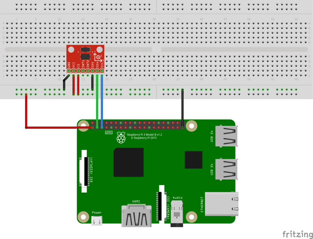
- First, link the GND pin of the sensor to one of the GNDs pins of the Raspberry Pi.
- The device can be powered by a 3.3V power source, so connect Vcc to one of the 3.3V pins of the Pi.
- SDA (SPI data) connects to SDA (pin 2 on the Pi).
- SCL (SPI clock) connects to SCL (pin 3 on the Pi).
Note: you usually have to add some pull-up resistors to SDA and SCL pins in order to be able to read something. Fortunately, this is already done for you on Raspberry Pi. Pins 2 and 3 both have a pull-up 1.8kOhm resistor. So, nothing more required from you here.
This complete Raspberry Pi pinout guide will help you get more details about each pin of the GPIO header.
Alright, the I2C hardware setup is done! Now you have to add 2 additional wires due to requirements of the ADXL345 device (here’s a resume of what’s written in the datasheet):
- (Specific to ADXL345) This device can be used with both I2C and SPI protocols. To enable I2C you have to connect the CS pin (Chip Select) to Vcc (3.3V here).
- (Specific to ADXL345) The device ID on the I2C bus will be set as 0x53 if SDO is linked to GND. For this tutorial we’ll decide to use this ID.
I2C Software setup on your Raspberry Pi
The setup is the same whether you use Raspbian or Ubuntu for Raspberry Pi.
By default I2C is disabled, you have to enable it yourself. There are many ways to do that, but the simplest one is just by editing a config file.
Open (with sudo) the “/boot/config.txt” file. Search for “i2c”, you’ll find this line:
#dtparam=i2c_arm=on
Just un-comment the line (remove the leading ‘#”), save and exit the file, and that’s it.
Make sure you reboot your Pi after you’ve done this, because the configuration is done during the boot. You can now use I2C!
Check that your device is detected
Once you’re done with hardware and software setup, and have reboot your Pi, run:
i2cdetect -y 1
     0  1  2  3  4  5  6  7  8  9  a  b  c  d  e  f
00:          -- -- -- -- -- -- -- -- -- -- -- -- --
10: -- -- -- -- -- -- -- -- -- -- -- -- -- -- -- --
20: -- -- -- -- -- -- -- -- -- -- -- -- -- -- -- --
30: -- -- -- -- -- -- -- -- -- -- -- -- -- -- -- --
40: -- -- -- -- -- -- -- -- -- -- -- -- -- -- -- --
50: -- -- -- 53 -- -- -- -- -- -- -- -- -- -- -- --
60: -- -- -- -- -- -- -- -- -- -- -- -- -- -- -- --
70: -- -- -- -- -- -- -- --
If you see this (device ID is 0x53) then your setup was correctly done.
Complete code example with WiringPi
Create a file named adxl345-i2c.cpp (or whatever you want).
Here’s the complete code to setup the I2C communication with WiringPi, read X, Y, and Z accelerations, and print the data. I’ll explain everything in a few seconds.
#include <iostream>
#include <thread>
#include <chrono>
#include <wiringPiI2C.h>

#define DEVICE_ID 0x53

#define REG_POWER_CTL   0x2D
#define REG_DATA_X_LOW  0x32
#define REG_DATA_X_HIGH 0x33
#define REG_DATA_Y_LOW  0x34
#define REG_DATA_Y_HIGH 0x35
#define REG_DATA_Z_LOW  0x36
#define REG_DATA_Z_HIGH 0x37

int main (int argc, char **argv)
{
    // Setup I2C communication
    int fd = wiringPiI2CSetup(DEVICE_ID);
    if (fd == -1) {
        std::cout << "Failed to init I2C communication.\n";
        return -1;
    }
    std::cout << "I2C communication successfully setup.\n";

    // Switch device to measurement mode
    wiringPiI2CWriteReg8(fd, REG_POWER_CTL, 0b00001000);

    while (1) {
        int dataX = wiringPiI2CReadReg16(fd, REG_DATA_X_LOW);
        dataX = -(~(int16_t)dataX + 1);

        int dataY = wiringPiI2CReadReg16(fd, REG_DATA_Y_LOW);
        dataY = -(~(int16_t)dataY + 1);

        int dataZ = wiringPiI2CReadReg16(fd, REG_DATA_Z_LOW);
        dataZ = -(~(int16_t)dataZ + 1);

        std::cout << "x: " << dataX << ", y: " << dataY << ", z: " << dataZ << "\n";
        std::this_thread::sleep_for(std::chrono::milliseconds(100));
    }

    return 0;
}
To compile, don’t forget to add -lwiringPi so you can link to the wiringPi library (which includes the I2C functionality).
g++ -o i2c_wiringpi_test adxl345-i2c.cpp -lwiringPi
./i2c_wiringpi_test
I2C communication successfully setup.
x: 0, y: 2, z: 34
x: 0, y: 2, z: 34
x: 0, y: 2, z: 34
^C
Code explained
Let’s break down the code line by line so you can understand what I wrote.
Setup
#include <iostream>
#include <thread>
#include <chrono>
#include <wiringPiI2C.h>
First, the include tags. Here we include the wiringPiI2C header, which contains all I2C functions related to WiringPi (see this header file on GitHub).
#define DEVICE_ID 0x53

#define REG_POWER_CTL   0x2D
#define REG_DATA_X_LOW  0x32
#define REG_DATA_X_HIGH 0x33
#define REG_DATA_Y_LOW  0x34
#define REG_DATA_Y_HIGH 0x35
#define REG_DATA_Z_LOW  0x36
#define REG_DATA_Z_HIGH 0x37
We use define tags to set the device ID and registers. This is a good practice, so you won’t mix up register addresses in your code and it will save you some debugging time.
Here we will use the POWER_CTL register, as well as the data registers for all 3 axis.
Init I2C communication
int main (int argc, char **argv)
{
    // Setup I2C communication
    int fd = wiringPiI2CSetup(DEVICE_ID);
    if (fd == -1) {
        std::cout << "Failed to init I2C communication.\n";
        return -1;
    }
    std::cout << "I2C communication successfully setup.\n";
The first thing we do is to setup the I2C communication with the wiringPiI2CSetup() function. This function takes the device ID as a parameter. It will try to connect to that device, and return a file descriptor.
Once the communication is successfully initiated, we can start interacting with the sensor.
Writing to a register
    // Switch device to measurement mode
    wiringPiI2CWriteReg8(fd, REG_POWER_CTL, 0b00001000);
To get acceleration data from the ADXL345 sensor, we need to change its mode from standby mode (default) to measurement mode.

As stated in the datasheet we have to set the ‘Measure Bit’ to 1, which is the 4th bit of the 8-bit register, hence the 0b00001000 value.
That’s a good opportunity here to write to a register with the WiringPi library.
The function wiringPiI2CWriteReg8() allows you to write a 8-bit register on the device. It takes 3 parameters: the file descriptor of the selected device, the register address, and the data to write.
You can also use wiringPiI2CWriteReg16() to write a 16-bit data to 2 adjacent registers. For example, if you use this function with the register address 0x04, then the first 8 bits will go to the 0x04 register, and the last 8-bits will be written into the 0x05 register.
Reading from a register
    while (1) {
        int dataX = wiringPiI2CReadReg16(fd, REG_DATA_X_LOW);
        dataX = -(~(int16_t)dataX + 1);

        int dataY = wiringPiI2CReadReg16(fd, REG_DATA_Y_LOW);
        dataY = -(~(int16_t)dataY + 1);

        int dataZ = wiringPiI2CReadReg16(fd, REG_DATA_Z_LOW);
        dataZ = -(~(int16_t)dataZ + 1);
The function wiringPiI2CReadReg8() allows you to read from a 8-bit register. You have to give the I2C device file descriptor, and the register address as parameters.
As you can notice, here we use the wiringPiI2CReadReg16() function instead. This will read 2 registers, the one that we give, and the following one. That’s very handy in that case. The acceleration data we want is split into 2 bytes, and is available on 2 adjacent registers. For example, the LSB (Least Significant Byte) of the X axis data is on register 0x32, and the MSB (Most Significant Byte) is on register 0x33.
Using wiringPiI2CReadReg16() allows us to write one function instead of 2, and to get directly the combined data.
Note that the read data is in 2’s complement, so we have to transform it to get negative numbers.
        std::cout << "x: " << dataX << ", y: " << dataY << ", z: " << dataZ << "\n";
        std::this_thread::sleep_for(std::chrono::milliseconds(100));
    }
    return 0;
}
Finally we print the result on the terminal, and we add a delay of 100 ms between 2 reads, so we are basically reading the value from the sensor at around 10Hz.
WiringPi I2C tutorial: Conclusion
The I2C functions inside the WiringPi library are really great to use in a Cpp program. They’re quite easy to understand and work well.
The WiringPi I2C functions you saw in this tutorial code example are pretty much all you need in order to communicate between your Raspberry Pi (as a master) and other devices (as slaves).