In this complete tutorial you will learn how to use an LED with Arduino. First, you will setup your circuit with an Arduino board and an LED, and then discover different ways to control the LED.
I will use Arduino Uno for the examples but the instructions here apply to any Arduino board.
If you want to just try the LED code on your Arduino, without doing the circuit, well, good news! You can just use the internal LED on pin 13 if you want (more about that in the following).
>> Watch this video as an additional resource (covers about half of the written article):
After watching the video, subscribe to the Robotics Back-End Youtube channel so you don’t miss the next tutorials!
You are learning how to use Arduino to build your own projects?
Check out Arduino For Beginners and learn step by step.
And now let’s get started!
Table of Contents
Create the Arduino LED circuit
For this circuit we will need:
- Arduino board.
- LED (any color, I will use red).
- Breadboard.
- 220 Ohm resistor (more info on the value later on).
- Some male to female wires.
Build the circuit
Here is the circuit.
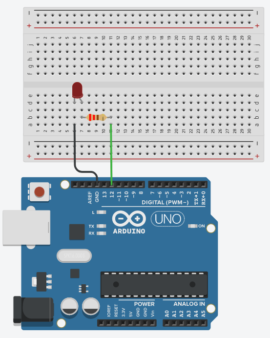
How to build the circuit:
- First make sure that the Arduino is powered off (no USB cable plugged to anything).
- Check the LED, you will see that one of the leg is shorter than the other one.
- Plug the shorter leg of the LED to a hole on the breadboard. Connect that leg to a GND pin of the Arduino, using a black cable if possible (convention for GND).
- Plug the longer leg of the LED to a different hole, on a different and independent line of the breadboard.
- Add a 220 Ohm resistor between this longer leg and a digital pin of the Arduino, using an additional colored wire (no red, no black) for convenience.
Here we choose digital pin 12 on the Arduino Uno.
Note: you could have chosen any of the digital pins ranging from 0-13, and also any of the analog pins, which you can use as digital pins. So, for the Arduino Uno, you get 20 possibilities. More info on Arduino Uno pins.
Why a 220 Ohm resistor for the LED?
This tutorial (and website) is more focused on software but I’ll make a quick parenthesis here to give you basic and simplified hardware explanation.
Basically, you want to limit the current that goes through the LED, so you will avoid damaging it and also damaging the pin on the Arduino board. The max value can depend, but let’s agree on 20mA max, which is 0.02A.
With the Ohm’s law, you get the relation between resistance, voltage, and current:
Voltage = Resistance * Current.
If you modify the order you get: Resistance = Voltage / Current.
So, if you want a max current of 0.02A, for a 5V voltage, you would need a 5V/0.02A = 250 Ohm resistor.
The thing is that, for LEDs, there is something more to take into account. This is the voltage drop of the LED. This voltage drop is going to be different for different colors, but let’s approximate it to 2V. So, the computation for the resistor becomes (5V – 2V)/0.02A = 150 Ohm.
With those values, you’d need a resistor which is at least 150 Ohm, so you can make sure the current stays under 20mA. The thing is that, finding a 150 Ohm resistor is not that common. 220 Ohm is more common, and it’s a higher value, so no problem. In fact, you could also use a 330 Ohm resistor and it will work, just with a slightly lower brightness, because the current will be lower. You could go as high as 1kOhm, for example if you want to add many LEDs, in order to reduce the overall current usage.
One thing to understand here: there’s no point in getting an exact resistor value. Any approximation that is above the minimum “safety” computation is fine.
OK, now that this is done, let’s go back to software.
Arduino code to power on an LED
Power on the LED with digitalWrite()
Let’s start with the most simple thing. Let’s say you just want to power on the LED when the Arduino program starts. This code will help us understand the setup and how digital pins work.
#define LED_PIN 12

void setup()
{
  pinMode(LED_PIN, OUTPUT);
  digitalWrite(LED_PIN, HIGH);
}

void loop() {}
This code is very short and will just power on the LED on pin 12. Let’s analyze it.
#define LED_PIN 12
First, and this is a best practice, we create a define for the pin number. This way, anytime we need to use this digital pin, we can write LED_PIN instead of the hard-coded number. In the future, if you ever need to use a different digital pin (for example 11), then you just need to change the number here and it will update it everywhere in your program.
void setup()
{
  pinMode(LED_PIN, OUTPUT);
We enter the void setup() function, which will be executed once at the beginning of the program.
Before we can actually use a digital pin, we need to set a mode. Basically you have 2 modes: output (if you want to control a component), or input (if you want to read some information from a component). Here, we want to control the LED, so we choose output. For that, we use the pinMode() function with 2 parameters:
- Pin number: here we use the LED_PIN that we previously defined.
- Mode: for output mode, we have to use OUTPUT (all uppercase).
After the execution of this line, the digital pin 12 will be set as output, and we can control the LED.
  digitalWrite(LED_PIN, HIGH);
}
Now, to control the LED, it’s very simple. We need to use the digitalWrite() function with 2 parameters:
- Pin number: again, we use the defined LED_PIN.
- State: we have 2 choices here. HIGH to power on the LED, and LOW to power it off.
So, after this line, the LED will be powered on.
Note: it’s important to call pinMode() before digitalWrite(), otherwise the LED won’t be powered on because the mode is not set.
void loop() {}
After the void setup() function is finished, we enter the void loop() and this function will be executed again and again, until you power off the Arduino.
Here we didn’t write anything in the void loop() because we just want to power on the LED and that’s it.
Test using only the built-in Arduino LED
If you don’t want to build the circuit, or want to test with something even simpler, you can use the built-in LED on the Arduino, which is soldered on digital pin 13.
You can use LED_BUILTIN which is already predefined for this LED.
void setup()
{
  pinMode(LED_BUILTIN, OUTPUT);
  digitalWrite(LED_BUILTIN, HIGH);
}

void loop() {}
And you’ll see the built-in LED powered on. Note: the location of the LED can vary depending on the type of your Arduino board.

Make the blink LED example
Now that you have the circuit and the code to setup the LED, let’s do something a bit more interesting.
Let’s make the LED blink, which means that we are going to:
- Power on the LED,
- wait,
- Power off the LED,
- wait,
- Go back to 1.
Here’s the code to do that (using our LED connected to digital pin 12).
#define LED_PIN 12

void setup()
{
  pinMode(LED_PIN, OUTPUT);
}

void loop()
{
  digitalWrite(LED_PIN, HIGH);
  delay(500);
  digitalWrite(LED_PIN, LOW);
  delay(500);
}
Let’s break down this code line by line.
#define LED_PIN 12
This is the same as before. We create a define so we can use the pin number later on in the code without having to hard-coding it.
void setup()
{
  pinMode(LED_PIN, OUTPUT);
}
In the void setup(), we initialize the mode for the pin to OUTPUT. Note that this is the only thing we do here.
void loop()
{
  digitalWrite(LED_PIN, HIGH);
  delay(500);
  digitalWrite(LED_PIN, LOW);
  delay(500);
}
And in the void loop(), we handle the blink mechanism. First we power on the LED with digitalWrite() and HIGH, then we wait using delay(). The delay() function will block the program for a given amount of time (in milliseconds). So, here, we block the program for 500 milliseconds, or 0.5 second.
After that, we power off the LED with digitalWrite() and LOW, and wait again for 0.5 seconds using delay(). This way, we have a complete cycle of “LED powered on” + “LED powered off”.
Once we exit the void loop(), it is called again, and thus the LED is powered on again, etc etc.
This blink example is maybe one of the most common example, but also super useful when you get started with Arduino. If you correctly understand the circuit and the code, you’ve already made big progress.
PWM functionality with Arduino LED
As for now, you’ve seen that you can control an LED with 2 states: HIGH (fully on with 5V), or LOW (fully off with 0V). What if you want to control the brightness of the LED, for example to 40% of the max brightness?
That’s where the PWM functionality is useful.
Very basically put, a PWM will allow you to output a voltage which is a percentage of the max voltage. So, if you want 40% brightness, you’d have to provide 40% of the voltage, which is 40% * 5V = 2V. Even if that sounds complicated, you will see that it’s super easy to do in the code.
What pins are compatible with PWM?
Not all pins are compatible with PWM functionality. Only the pins with a “~” next to the number are compatible. On Arduino Uno, you have pins 3, 5, 6, 9, 10 and 11.
As our LED is currently connected to digital pin 12, which doesn’t support PWM, we will need to modify the circuit.
First, power off the Arduino, and then simply change the wire from pin 12 to pin 11 (or any other compatible pin).
Power on the LED with analogWrite()
Let’s write the code to power on the LED, but with just 40% of the max voltage.
#define LED_PIN 11

void setup()
{
  pinMode(LED_PIN, OUTPUT);
  analogWrite(LED_PIN, 102);
}

void loop() {}
First, we update the define line with the pin number 11 instead of 12. As you can see this is very practical, as we don’t have to change the number anywhere else in the code.
Then, instead of using digitalWrite(), we use analogWrite() with 2 parameters:
- Digital pin, here LED_PIN as previously defined.
- Percentage of the voltage, scaled to 0-255 (one byte of data). If we want 40% we need to do 255 * 0.4 = 102. This will correspond to an output of 5V * 0.4 = 2V.
You can use any value between 0 and 255 to try different intensities for the LED.
Note: even if you are connected to a PWM compatible pin and using analogWrite(), you can still use digitalWrite() any time you want. Also:
- using analogWrite(LED_PIN, 0) is the same as digitalWrite(LED_PIN, LOW),
- and analogWrite(LED_PIN, 255) is the same as digitalWrite(LED_PIN, HIGH).
Important note: do not be confused between PWM pins and analog pins. Basically you can use:
- digitalWrite() with any digital pin and any analog pin (to fully power on/off an LED).
- analogWrite() with only digital pins which have a “~” next to the number (to change the brightness of an LED for example).
This can be confusing because you can use analogWrite() for certain digital pins, but on the other hand, you can’t use the analogWrite() on analog pins. There is no real sense to make here, this is just how it has been defined. The “analogWrite()” function could have been named “pwm()” or something similar, but now it’s probably too late to change this kind of convention.
Make the LED fade in/fade out
Let’s try something more interesting with PWM. Here we want to make the LED fade in (which means the brightness will slowly increase until the max), and then fade out (brightness will slowly decrease), so we can create a nice effect with the LED.
#define LED_PIN 11

void setup()
{
  pinMode(LED_PIN, OUTPUT);
}

void loop()
{
  for (int i = 0; i <= 255; i++) {
    analogWrite(LED_PIN, i);
    delay(10);
  }

  for (int i = 255; i >= 0; i--) {
    analogWrite(LED_PIN, i);
    delay(10);
  }
}
Let’s analyze this code.
#define LED_PIN 11

void setup()
{
  pinMode(LED_PIN, OUTPUT);
}
Nothing new here, we define the pin for the LED, and then initialize the mode to OUTPUT. We don’t do anything else in the void setup().
void loop()
{
  for (int i = 0; i <= 255; i++) {
    analogWrite(LED_PIN, i);
    delay(10);
  }
The void loop() is separated in 2. Here we make the LED “fade in”, which means that we apply all values from 0 to 255 to the pin, with analogWrite(). Between each update we add a small delay of 10 milliseconds, so we have the time to see what’s happening.
Once we reach 255, the for loop ends.
  for (int i = 255; i >= 0; i--) {
    analogWrite(LED_PIN, i);
    delay(10);
  }
}
Now, we do the same thing but on the way back to 0. This for loop will start at 255 and each time will decrease the index. We make the LED “fade out”, also with a small delay.
Once the for loop ends, the brightness of the LED is 0 (LED powered off), and the void loop() starts again to “fade in”.
Working with multiple LEDs
For now I’ve made examples with just one LED. What if you want to use several LEDs on your Arduino circuit?
Arduino Circuit with 3 LEDs
Let’s create a circuit with 3 LEDs.
As you can see, once you know how to connect 1 LED in your Arduino circuit, adding more LEDs is not that hard. You just have to follow the same recipe:
- Connect the shorter leg to the common ground (GND).
- Connect the longer leg to a digital pin of the Arduino, with a 220 Ohm resistor in between.
Also, instead of directly connecting each shorter leg to a different GND pin, here we use the breadboard in a smart way. We connect all shorter legs to the “minus” line (or the blue line in some boards), and from there, we just plug one wire between this line and a GND pin of the Arduino.
Arduino code for 3 LEDs
Let’s make a very simple application: we want first the red LED to be powered on, then the yellow one, then the green one, and back to the red one.
#define LED_PIN_1 11
#define LED_PIN_2 10
#define LED_PIN_3 9

void setup()
{
  pinMode(LED_PIN_1, OUTPUT);
  pinMode(LED_PIN_2, OUTPUT);
  pinMode(LED_PIN_3, OUTPUT);
}

void loop()
{
  digitalWrite(LED_PIN_1, HIGH);
  digitalWrite(LED_PIN_2, LOW);
  digitalWrite(LED_PIN_3, LOW);
  delay(1000);
  digitalWrite(LED_PIN_1, LOW);
  digitalWrite(LED_PIN_2, HIGH);
  digitalWrite(LED_PIN_3, LOW);
  delay(1000);
  digitalWrite(LED_PIN_1, LOW);
  digitalWrite(LED_PIN_2, LOW);
  digitalWrite(LED_PIN_3, HIGH);
  delay(1000);
}
Nothing really complicated: for the setup we just duplicate the code for each new LED. We add a define and we setup the mode with pinMode().
Then, well you can use digitalWrite() on each LED – and analogWrite() if the pin is PWM compatible – whenever you want. In this case we just power on each LED, once at a time, with a 1 second delay.
Going further with Arduino and LEDs
In this Arduino LED tutorial you’ve seen how to create a circuit with a LED, and how to write code to control it. As you’ve seen, even if we keep the examples at a basic level, there are quite a few things you can do with LEDs.
The amount of applications where you will use LEDs is endless. LEDs can be used to display some information (ex: green LED for a traffic light), to warn the user (ex: red LED as a warning that a robot is close from a collision), to add some light for a camera, or even just for nice looking purpose.
Now, to go further with LEDs, here are a few interesting resources which will expand your knowledge on the programming side, but also if you decide to add more components into your circuit and make it more complete: