In this tutorial I will show you how to control an LED with your Raspberry Pi 4 (also works with Raspberry Pi 3 and 2) and Python 3.
Controlling an LED is the first step you can take to discover how GPIOs work and what to do with them. After this you’ll be able to take other steps to build cool projects with your Pi.
So, first we’ll do a little bit of setup, and then dive into the Python 3 program. If you’ve already made the hardware setup, just skip the first section of the tutorial.
And now, let’s get started!
>> Here is a video version of this tutorial, as an additional resource:
You are learning how to use Raspberry Pi to build your own projects?
Check out Raspberry Pi For Beginners and learn step by step.
After watching the video, subscribe to the Robotics Back-End Youtube channel so you don’t miss the next tutorials!
Table of Contents
Hardware setup – Make a circuit with your Raspberry Pi and the LED
First of all, make sure your Raspberry Pi is powered off. This is very important. Never plug/unplug any hardware component while your Pi is powered on. You could damage it – for example with an ESD (Electro Static Discharge) – or even completely destroy the CPU if you make a wrong pin connection.
But, don’t worry too much either: if you’re always extra careful and double check everything you do, nothing wrong will happen!
To build this circuit you will need:
- A breadboard
- A Raspberry Pi with GPIO header
- 1 LED – the color doesn’t matter
- 1 resistor: any value between 330 Ohm to 1 k Ohm will be fine. For this example I use 1 k Ohm. To know which color corresponds to which value, check out this website.
- A set of male to female wires.
Here’s the schematics to plug an LED to your Raspberry Pi:
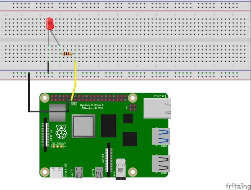
Now here are the steps to build the circuit:
- Connect one wire between one GND (ground) pin of the Raspberry Pi and the blue line of the breadboard.
- Take the LED and check the 2 legs. You will see that one is shorter than the other. Plug the shorter leg to the blue line (now connected to GND), and the longer to any other connector. You can either directly connect the shorter leg to the blue line, or add an additional short male-to-male connector (like in the picture), the result is the same.
- Plug one leg of the resistor to the same line as the longer leg of the LED, and the other leg of the resistor to a different line.
- Finally, to close the circuit plug one wire between the same line as the other leg of the resistor, and the GPIO number 17 (more on Raspberry Pi pins and GPIOs). This is the 6th pin on the GPIO header, starting from the left, on the inside side.
Software setup – Raspberry Pi OS
If you haven’t done it yet, first, install Raspberry Pi OS on a micro SD card. Download the Raspberry Pi Imager and plug your micro SD to your computer.

Select “Raspberry Pi OS” as the operating system, and click on “Write” to flash it on your SD card. Then, you can put the micro SD card into your Raspberry Pi and finish the installation with, or without an external monitor.
Control the LED with Python 3 on Raspberry Pi OS
Now that everything (hardware + software) is correctly setup, you can start to control the LED on Raspberry Pi with Python3.
Open Thonny IDE on Raspberry Pi OS (Menu > Programming > Thonny Python IDE) or any other IDE/text editor you like.
Simple control of the LED
Let’s write a minimal program to simply power on and power off the LED.
import RPi.GPIO as GPIO
import time

LED_PIN = 17

GPIO.setmode(GPIO.BCM)
GPIO.setup(LED_PIN, GPIO.OUT)

GPIO.output(LED_PIN, GPIO.HIGH)
time.sleep(1)
GPIO.output(LED_PIN, GPIO.LOW)

GPIO.cleanup()
This program will power on the LED for one second, and then power it off. Let’s break the program down line by line.
import RPi.GPIO as GPIO
import time
First we import the RPi.GPIO Python module which will allow us to control all GPIOs from the Raspberry Pi’s GPIO header. You’ll see that this module is quite easy to use.
We also import the time module which we’ll use later to wait for 1 second.
LED_PIN = 17
As a best practice, we create a “constant” global variable containing the GPIO number for the LED. This will allow you to use the variable name instead of the number directly. You will make less mistakes, and in the future if you want to change the LED’s GPIO, you just have to update this variable.
GPIO.setmode(GPIO.BCM)
This line should be the first line you execute with the RPi.GPIO module. This will allow you to use the GPIO numbers instead of the “standard” pin numbers.
For example, you can see here that GPIO 17 corresponds to pin number 11. And the pin number 17 is a 3.3V power pin.
If you don’t set the mode to BCM, then you might end up controlling the wrong pin for your LED.
GPIO.setup(LED_PIN, GPIO.OUT)
OK, now we can start setting up the GPIO for the LED. We need to use the GPIO.setup() function and provide the mode of the GPIO: either GPIO.OUT for output, or GPIO.IN for input. As we want to tell the LED what to do, instead of reading its state, we have to use GPIO.OUT.
GPIO.output(LED_PIN, GPIO.HIGH)
time.sleep(1)
GPIO.output(LED_PIN, GPIO.LOW)
All the setup is finished, we can power on/off the LED. To do that you just have to use one simple command: GPIO.output(), with either GPIO.HIGH to power on the LED, or GPIO.LOW to power off the LED.
GPIO.cleanup()
And we finish the program by cleaning up the GPIOs, with GPIO.cleanup(). This line is super important. It will reset all states and modes for all GPIOs, which can prevent you from having errors in future programs. Or even worse, fry your Raspberry Pi (if now you put a push button in GPIO 17 and try to read from it, and the GPIO hasn’t been cleaned up, then you’ll have a problem).
Note: in this situation, writing GPIO.output(LED_PIN, GPIO.LOW) was not mandatory because GPIO.cleanup() will do that automatically.
Make the LED blink
Let’s improve the program by making the LED blink indefinitely.
import RPi.GPIO as GPIO
import time

LED_PIN = 17

GPIO.setmode(GPIO.BCM)
GPIO.setup(LED_PIN, GPIO.OUT)

while True:
    GPIO.output(LED_PIN, GPIO.HIGH)
    time.sleep(1)
    GPIO.output(LED_PIN, GPIO.LOW)
    time.sleep(1)

GPIO.cleanup()
The setup is the same (line 1-7). Then, we simply alternate between GPIO.HIGH and GPIO.LOW every second, inside an infinite loop. If you’ve ever used an Arduino board, this example is the same as the Blink LED example you can find with Arduino.
Now, this program works but there’s a small issue we’ll need to fix.
What is this issue?
Well, when you run the program you can see that it doesn’t exit by itself – because of the infinite loop. So, you have to stop/kill the program yourself, either by clicking on the “stop” button on Thonny IDE, or pressing CTRL+C in the shell panel (also if you’ve run the Python program directly from the terminal).
And, when you kill the program, the line GPIO.cleanup() won’t have the chance to be executed. So, the GPIO 17 won’t be reset and cleaned up.
If you start the program again after killing it, it still works well and there is no risk for your Raspberry Pi (because you’re using the GPIO for the same purpose), but you’ll get this warning:
RuntimeWarning: This channel is already in use, continuing anyway. Use GPIO.setwarnings(False) to disable warnings.
GPIO.setup(LED_PIN, GPIO.OUT)
So, as suggested, you could use GPIO.setwarnings(False) at the beginning of your program so you don’t have the warning again. But that’s not a real solution to our problem.
Make sure the LED GPIO is cleaned up every time
To be sure that the LED GPIO (and all other GPIOs) is cleaned up every time we kill the Python program, we’ll use a try/catch structure, to be able to “catch” the CTRL+C, so we can do an action just before the program exits.
import RPi.GPIO as GPIO
import time

LED_PIN = 17

GPIO.setmode(GPIO.BCM)
GPIO.setup(LED_PIN, GPIO.OUT)

try:
    while True:
        GPIO.output(LED_PIN, GPIO.HIGH)
        time.sleep(1)
        GPIO.output(LED_PIN, GPIO.LOW)
        time.sleep(1)
except KeyboardInterrupt:
    GPIO.cleanup()
Here we haven’t changed anything in the setup, and the main functionality stays the same.
What we’ve done is to put the infinite loop inside a try/catch (try/except in Python3) structure.
Here’s what will happen when you run this program:
- First (line 1-7), the LED GPIO will be setup.
- Then, we enter the while loop and make the LED blink.
- Because the while loop is inside a “try” block, then when we press CTRL+C, we will be able to catch the corresponding exception (of type KeyboardInterrupt).
- We add an “except KeyboardInterrupt” to execute some code when the exception has been caught.
- In this “except” block, we use GPIO.cleanup().
- After that, the program continues it’s execution after the try/catch. In this case, because there’s nothing more, the program exits.
And… problem solved!
Note: if you’re using the Thonny Python IDE, to kill the program you’ll have to select the Shell panel and press CTRL+C. If you stop the program with the red “stop” button, the KeyboardInterrupt won’t be triggered and your GPIO won’t be cleaned up.
Conclusion – Control LED from Raspberry Pi
In this tutorial you’ve seen how to setup and control an LED from your Raspberry Pi 4 and Python 3.
With a few code iterations you’ve understood what are the main important things you should do in your programs so it’s correctly setup, and so the LED’s GPIO will be correctly cleaned up.
From now on you can use this code structure for one or multiple LEDs. But it doesn’t end there: in fact, you can use that structure for any piece of hardware you want to control from your Raspberry Pi’s GPIO header.