In this tutorial I’ll show you how to communicate between a Raspberry Pi and an Arduino board via Serial communication.
First, I’ll quickly explain what is Serial communication. Then you’ll see how to setup your hardware and software, and we’ll dive into the Python code (Cpp for Arduino). A basic example at first, leading to a more complete application using a Raspberry Pi, an Arduino, and other electronic devices.
This tutorial will work with a Raspberry Pi 4 (and earlier: 3B, 3B+) board, and any Arduino board. I’ll use mostly Arduino Uno but will give more details about the differences between Arduino boards when it comes to Serial communication.
>> I also made a complete step by step video tutorial, to go from zero to bidirectional communication with Serial in 1h – check that out if you like to learn with video content:
After watching the video, subscribe to the Robotics Back-End Youtube channel so you don’t miss the next tutorials!
You are learning how to use the combo Raspberry Pi + Arduino to build your own projects?
Check out Raspberry Pi and Arduino and learn step by step.
When working with electronic devices, communication is key. Each device – on top of doing well what it’s supposed to do – must be able to clearly communicate with other devices. That’s one of the most important thing to work on in order to switch from a very basic application to more complex ones.
Table of Contents
What is Serial communication (with UART)
Serial communication is simply a way to transfer data. The data will be sent sequentially, one bit at a time (1 byte = 8 bits), contrary to parallel communication, where many bits are sent at the same time.
UART protocol
More specifically, when you use Serial with Arduino and Raspberry Pi, you’re using the UART protocol. UART means “Universal Asynchronous Reception and Transmission”.
Basically it’s an asynchronous multi-master protocol based on the Serial communication, which will allow you to communicate between the 2 boards. Be reassured, there are libraries that will handle all the low layers for you.
Multi-master means that all connected devices will be free to send data when they want. This is one of the main difference with master-slaves protocols, where only the master device can initiate a communication. Usually you’ll use other protocols such as I2C and SPI when you need master-slaves configurations: for example when you have one Arduino board and multiple sensors or actuators.
The Arduino Uno board has one UART that you can use either with a USB cable or from the RX/TX pins (don’t use it with both at the same time). Some boards have more available UARTs. For example the Arduino Mega has different Serials (Serial, Serial1, Serial2, Serial3) and the Arduino Zero has a native USB port only (use SerialUSB instead of Serial).
On the Raspberry Pi, you can connect many Serial devices on the USB ports. Each will have a different device name (we’ll see how to find them later in this tutorial). You can also use the GPIOs (RX0/TX0) for an additional UART.
You probably already know Serial communication
You’ve certainly already used Serial communication many times. I’m sure you already know the Arduino Serial library, which allows you to log what’s happening in your code and get user input. When you use the Serial monitor, well, basically your Arduino IDE initiates a Serial communication with your Arduino. You can receive and send data directly from the Serial monitor.
What we’ll do here is almost the same, except that instead of your Arduino IDE, the other side of the Serial communication will be a Raspberry Pi board. We’ll have to do some setup and write some code to make it work. Then, both Raspberry Pi and Arduino will be able to send messages to each other.
Let’s now see how to physically connect the 2 boards together.
Hardware setup for Serial communication
There are 2 ways to connect your Raspberry Pi and Arduino for Serial communication.
Serial via USB
The easiest way is to use a USB cable between both board.
On the Raspberry Pi side, a simple USB connector is all you need. You can choose any of the 4 USB ports available on the board.
For Arduino, you will use the USB port that you use to upload code from your computer (with the Arduino IDE) to your board. Here the USB connector will depend on which version you have. For boards like Arduino Uno and Mega, the connector will be different from Arduino Nano, and from Arduino Zero.
For this example I’ve used an Arduino Uno board.
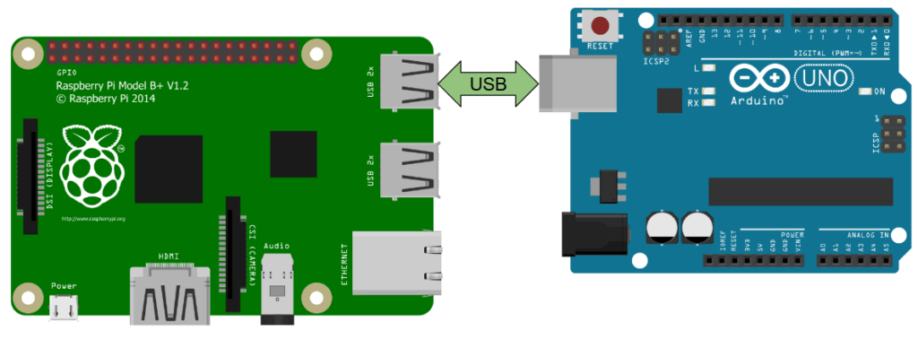
As you can see, it’s the simplest hardware connection you can make between Raspberry Pi and Arduino.
Note: you will first need to connect your Arduino to your computer, so you can upload the code into the board. After that, connect the USB cable to the Raspberry Pi. The Raspberry Pi will power the Arduino via this cable.
Serial via GPIOs
To make a Serial connection you can also use plain wires between the Raspberry Pi GPIOs and the Arduino pins.

Depending on your Arduino board you might need to use a voltage level-shifter. The Raspberry Pi is operating at 3.3V. For Arduino boards like Due, 101, it will be fine because they also use 3.3V.
But, for many Arduino, such as Uno, Mega, Leonardo, Nano, and many more, the board is operating at 5V. Thus, you need a 3.3V/5V level-shifter to protect the Raspberry Pi when connecting RX and TX (more info on Raspberry Pi pins and Arduino Uno pins).
For the rest of this tutorial we’ll use the setup with the USB cable. This will be easier to manage and unless you have a good reason not too, you should prefer using the USB cable instead of plain gpios for Serial communication.
Raspberry Pi Software setup
You don’t need any special setup for Arduino. Just make sure you have downloaded and installed the Arduino IDE.
Now, on your Raspberry Pi, a few things are required to make the communication work.
Connect to your Raspberry Pi, either via ssh, or by plugin a screen+mouse+keyboard, and open a terminal. If you haven’t installed an OS on your Pi yet, you can install Raspbian or Ubuntu very easily on a SD card.
Detect the Arduino board
When connecting the Arduino with a USB cable, you should see it appear as /dev/ttyACM0, or /dev/ttyUSB0 (sometimes the number can be different, for example /dev/ttyACM1).
Simply run ls /dev/tty* and you should see it. At this point if you’re not sure which device is the Arduino board, simply disconnect the board (remove the USB cable), and run ls /dev/tty* again. This way you will easily spot the serial device name of your Arduino.
Hardware permissions for Serial
Also, you may want to add your user to the dialout group, to avoid errors such as: serial.serialutil.SerialException: [Errno 13] could not open port /dev/ttyACM0: [Errno 13] Permission denied: ‘/dev/ttyACM0’.
$ sudo adduser your_username dialout
This will make sure you have access to Serial devices (/dev/ttyACMx, /dev/ttyUSBx, …).
After you’ve added yourself to the dialout group, you need to reboot your Pi (or at least logout/login) to apply the change – learn more about Raspberry Pi hardware permissions.
Install Python Serial library on Raspberry Pi
You need to install a library to be able to use the Serial interface with Python.
For this tutorial we’ll use the pySerial library (documentation for Python 3). To install it:
python3 -m pip install pyserial
This Python library is well-known and used in a lot of applications.
When installing, if you get an error such as “/usr/bin/python3: No module named pip”, then you need to install pip first with sudo apt install python3-pip.
Simple Serial communication from Arduino to Raspberry Pi
Let’s start with a very simple program.
Arduino code
Upload this code from your computer to your Arduino, using the Arduino IDE.
void setup() {
  Serial.begin(9600);
}

void loop() {
  Serial.println("Hello from Arduino!");
  delay(1000);
}
First, we initialize the Serial communication, and choose a baud rate, here 9600. 9600 is a commonly used baud rate, and also a pretty low one. In your future applications you can use a baud rate of 57600 or even 115200 without any problem. For this tutorial we’ll continue with 9600.
Every second we make the Arduino send a string with Serial.println(). the println() function will add a newline character ‘\n’ at the end of the string.
You can open the Serial monitor to see the string on your computer.
Raspberry Pi Python code
#!/usr/bin/env python3
import serial

if __name__ == '__main__':
    ser = serial.Serial('/dev/ttyACM0', 9600, timeout=1)
    ser.reset_input_buffer()

    while True:
        if ser.in_waiting > 0:
            line = ser.readline().decode('utf-8').rstrip()
            print(line)
So, what does this code do?
#!/usr/bin/env python3
import serial
First, we import the serial library which we previously installed.
if __name__ == '__main__':
    ser = serial.Serial('/dev/ttyACM0', 9600, timeout=1)
The Serial communication is initialized by calling serial.Serial() along with a few parameters:
- Serial device name for the Arduino: usually ‘/dev/ttyACM0’, ‘/dev/ttyUSB0’, or similar.
- Baud rate: this parameter is very important. You need to use the same baud rate as the one you used on Arduino, or else everything you’ll read and write will be garbage. So, we choose 9600 as we did in the Arduino sketch.
- timeout: this is a timeout for read operations. Here we set it to 1 second. It means that when we read from Serial, the program won’t be stuck forever if the data is not coming. After 1 second or reading, if not all bytes are received, the function will return the already received bytes.
So, serial.Serial() returns an object that you can use for all your Serial operations. We store it in the ‘ser’ variable.
ser.reset_input_buffer()
Then we use the reset_input_buffer() function. This will flush any byte that could already be in the input buffer at that point, so it will avoid receiving weird/not useful/not complete data at the beginning of the communication.
    while True:
        if ser.in_waiting > 0:
            line = ser.readline().decode('utf-8').rstrip()
            print(line)
In an infinite loop (think of the loop() function in the Arduino sketch), we check if some data is available with the in_waiting attribute (don’t put parenthesis, this is not a function). If yes, we can read the data.
The readline() function will read all bytes until a newline character is detected.
If we just printed what we received we would see b’Hello from Arduino!\r\n’. You receive bytes when you read from Serial, and you have to convert (decode) those bytes into the appropriate data type. So, we use decode(‘utf-8’) – you can also use decode(‘ascii’) – to decode the received data to a string.
Finally, the rstrip() function is specific to strings, it allows you to remove any trailing characters (newline, carriage return). This way we can remove the ‘\r’ and ‘\n’ and get a proper string.
Note: here we read a complete line every time. If you want to read a certain amount of bytes – one or more – use the read(size=1) function.
Testing Serial communication
Now, unplug your Arduino board from your computer and connect it to your Raspberry Pi board.
The Arduino code is already running, as soon as it’s powered up.
On the Raspberry Pi, make the Python file executable and launch it.
$ chmod +x receive_serial_data_from_arduino.py
$ ./receive_serial_data_from_arduino.py
Hello from Arduino!
Hello from Arduino!
Hello from Arduino!
It works! The string sent by Arduino every second is displayed on the Raspberry Pi terminal.
Bidirectional Serial communication between Raspberry Pi and Arduino
Let’s make things a little bit more interesting. You’ve seen how to send data from Arduino to Raspberry Pi. In this part you’ll see how to talk from Raspberry Pi to Arduino. Thus you’ll have both sides of the communication and you’ll be able to create programs that wait for each other’s input.
Arduino code
void setup() {
  Serial.begin(9600);
}

void loop() {
  if (Serial.available() > 0) {
    String data = Serial.readStringUntil('\n');
    Serial.print("You sent me: ");
    Serial.println(data);
  }
}
Here we check if the Arduino has received data with Serial.available(). This will give you the number of bytes already arrived and stored in the receive buffer.
If some data has arrived, we use Serial.readStringUntil() with a newline character ‘\n’ to get the next line. This is similar to the readline() function. All the bytes received until ‘\n’ are automatically converted and added in an Arduino String object.
Then, we just print back the data we received, with an additional piece of text.
Note: if you want to read bytes one by one, you can do so with the Serial.read() function. Then you’ll have to convert this(those) byte(s) if needed: int, String, etc.
Raspberry Pi Python code
#!/usr/bin/env python3
import serial
import time

if __name__ == '__main__':
    ser = serial.Serial('/dev/ttyACM0', 9600, timeout=1)
    ser.reset_input_buffer()

    while True:
        ser.write(b"Hello from Raspberry Pi!\n")
        line = ser.readline().decode('utf-8').rstrip()
        print(line)
        time.sleep(1)
Use the pySerial function write() to send data to the Arduino. Here you can see that I’ve added a ‘b’ before the string to send. This will encode the string to bytes, because you can only send bytes through Serial. Any data which is not a byte or byte array must be converted before being sent. If you just try to send the string like that, you’ll get this error ” TypeError: unicode strings are not supported, please encode to bytes: ‘Hello from Raspberry Pi!’ ”
Note: instead of ser.write(b"Hello from Raspberry Pi!\n") you could’ve written ser.write("Hello from Raspberry Pi!\n".encode('utf-8')) or ser.write("Hello from Raspberry Pi!\n".encode('ascii')). This will do the same thing. The encode() function will take the string and encode it for Serial.
Also, we add a newline character ‘\n’ because that’s what the Arduino is expected to end its reading with Serial.readStringUntil(‘\n’).
Then, we do the same thing as we did before: we read a line, decode it to string, and remove any trailing character. We’re not using the ser.in_waiting here, because for this specific application we know that the Arduino will send back some data just after it has received the string. Also, we have a 1 second timeout to avoid being stuck on this line.
Finally, we print the received string and wait for 1 second with time.sleep() before sending the next string over Serial.
Testing bidirectional Serial communication
On your Raspberry Pi, make your Python file executable and launch it.
$ chmod +x bidirectional_serial_communication.py
$ ./bidirectional_serial_communication.py
You sent me: Hello from Raspberry Pi!
You sent me: Hello from Raspberry Pi!
You sent me: Hello from Raspberry Pi!
Success! The Arduino received the string, and sent it back with a few more words. Then the Raspberry Pi received and printed the final string.
Raspberry Pi Arduino Serial communication: Application example
Now that you know how to setup your Arduino and Raspberry Pi for Serial communication, and write programs to talk between each board, let’s create a more complex application.
In this application, 4 LEDs and one push button will be connected to the Arduino board.
The Raspberry Pi and Arduino will be connected with a USB cable and use Serial communication to talk to each other.
Here’s the result we want to get:
- When the push button is pressed, the Arduino will send a notification to the Raspberry Pi (a simple byte).
- The Raspberry Pi will then compute a random integer number between 1 and 4, and send it to the Arduino.
- The Arduino will power on the LED related to this number, and power off the other LEDs.
This will make you practice on the communication and synchronization of tasks between Arduino and Raspberry Pi.
If you arrived at this point of the tutorial (congrats!) I encourage you to try to write the code by yourself before you read the code I’ve provided below. Also, there is not only one possible code to meet those requirements, so your code might be different from mine, it’s totally OK. You can get help from the Arduino Serial reference and the pySerial API reference.
Schematics
To make this circuit:
- Connect 4 LEDs to pins 9-12. Add a 220 Ohm resistor for each LED between the longer leg and the digital pin. The shorter leg is connected to the ground.
- Add a push button with a 10kOhm resistor connected to the ground (pull-down resistor). One side of the button is connected to 5V, the other to digital pin 5 for reading.
- Don’t forget to make a common ground between all components: The Arduino board, the 4 LEDs and the push button. Don’t add any power supply if you haven’t at least correctly connected the grounds.
- Connect the Arduino and Raspberry Pi via a USB cable, for the Serial communication (the USB cable already manages the ground connection between your 2 boards).
Arduino code
#define LED_1_PIN 9
#define LED_2_PIN 10
#define LED_3_PIN 11
#define LED_4_PIN 12

#define BUTTON_PIN 5

byte lastButtonState = LOW;
byte currentButtonState = LOW;
unsigned long lastButtonDebounceTime = 0;
unsigned long buttonDebounceDelay = 20;

void powerOffAllLEDs()
{
    digitalWrite(LED_1_PIN, LOW);
    digitalWrite(LED_2_PIN, LOW);
    digitalWrite(LED_3_PIN, LOW);
    digitalWrite(LED_4_PIN, LOW);
}

void setup()
{
  Serial.begin(9600);
  pinMode(LED_1_PIN, OUTPUT);
  pinMode(LED_2_PIN, OUTPUT);
  pinMode(LED_3_PIN, OUTPUT);
  pinMode(LED_4_PIN, OUTPUT);
  pinMode(BUTTON_PIN, INPUT);

  powerOffAllLEDs();
}

void loop()
{
  byte readValue = digitalRead(BUTTON_PIN);

  if (readValue != lastButtonState) {
    lastButtonDebounceTime = millis();
  }

  if (millis() - lastButtonDebounceTime > buttonDebounceDelay) {
    if (readValue != currentButtonState) {
      currentButtonState = readValue;
      if (currentButtonState == HIGH) {
        Serial.write(18);
      }
    }
  }

  lastButtonState = readValue;

  if (Serial.available() > 0) {
    int ledNumber = Serial.read() - '0';

    powerOffAllLEDs();

    switch (ledNumber) {
      case 1:
        digitalWrite(LED_1_PIN, HIGH);
        break;
      case 2:
        digitalWrite(LED_2_PIN, HIGH);
        break;
      case 3:
        digitalWrite(LED_3_PIN, HIGH);
        break;
      case 4:
        digitalWrite(LED_4_PIN, HIGH);
        break;
      default:
        // wrong pin number, do nothing
        // all LEDs will be powered off
        break;
    }
  }
}
In the setup() function we initialize the pin modes for all 4 LEDs and the push button. We also make sure all LEDs are powered off.
Then in the loop() we do 2 things: handling the push button and managing the 4 LEDs. Both actions are done one by one, but they are handled very fast so it’s just as if they were happening at the same time. That’s a case of multitasking an Arduino program.
First action: handling the push button.
byte readValue = digitalRead(BUTTON_PIN);

if (readValue != lastButtonState) {
  lastButtonDebounceTime = millis();
}

if (millis() - lastButtonDebounceTime > buttonDebounceDelay) {
  if (readValue != currentButtonState) {
    currentButtonState = readValue;
    if (currentButtonState == HIGH) {
      Serial.write(18);
    }
  }
}

lastButtonState = readValue;
We need to debounce the button to avoid unwanted values. When we find out that the button is pressed, we can send some data to the Raspberry Pi via Serial.
Here I’ve used the Serial.write() function: it sends a byte or series of bytes. This is different from Serial.print() which will make the output nice to see on the Serial monitor. As we’re talking to another machine and not a human, no problem with that.
The number we send here is 18. This is just a random number that we’ll associate with the state “button has been pushed”, so when the Raspberry Pi will receive a number, it will check if it’s equal to 18. You could imagine sending different actions or messages via Serial, using different numbers.
Note: usually you can also use Arduino interrupts to know when a button has been pushed. If you do so, don’t use the Serial library in the interrupt. If you absolutely have to use interrupts, then set a flag inside the interrupt (a simple boolean variable), and use Serial inside your loop() function.
And the second action: managing the 4 LEDs.
  if (Serial.available() > 0) {
    int ledNumber = Serial.read() - '0';

    powerOffAllLEDs();

    switch (ledNumber) {
      case 1:
        digitalWrite(LED_1_PIN, HIGH);
        break;
      case 2:
        digitalWrite(LED_2_PIN, HIGH);
        break;
      case 3:
        digitalWrite(LED_3_PIN, HIGH);
        break;
      case 4:
        digitalWrite(LED_4_PIN, HIGH);
        break;
      default:
        // wrong pin number, do nothing
        // all LEDs will be powered off
        break;
    }
  }
First we check if the Arduino has received some data from the Raspberry Pi over the Serial communication.
If yes, we read the next byte with Serial.read(). Here you can notice a small trick, consisting of subtracting with ‘0’, which will convert the character to the number it represents – in this case an integer.
After that it’s quite simple. We power off all LEDs, and then power on only the LED associated with the number: 1, 2, 3 or 4. In case a wrong value is sent, no LED will be powered on.
Raspberry Pi Python code
#!/usr/bin/env python3
import serial
import random

if __name__ == '__main__':
    ser = serial.Serial('/dev/ttyACM0', 9600, timeout=1)
    ser.reset_input_buffer()

    while True:
        number = ser.read()
        if number != b'':
            if int.from_bytes(number, byteorder='big') == 18:
                led_number = random.randint(1,4)
                print("Button has been pressed.")
                print("Sending number " + str(led_number) + " to Arduino.")
                ser.write(str(led_number).encode('utf-8'))
First we add one import line: the Python random library.
In the infinite loop (“while True”), we first read one byte from Serial. The timeout is set at 1 second. If nothing is received after one second, the read() function will return b”.
So we check if what we received is simply empty (b”) or if there was really something. In this latter case, we convert the data we received to an integer so we can use in the code. For that we use the function int.from_bytes(), which will decode b’0x12′ (the hexadecimal representation of 18 is 0x12) to 18.
As you can see we check that the number is 18 to continue the action. If you have different commands to handle, using a different number for each command is a good practice.
We choose a random number between 1 and 4 to determine which LED to power on. Then we send it with the pySerial write() function. To send an int via Serial, we first convert it as a string with str(), and then encode it with encode(‘utf-8’).
Testing the application
Now you can connect the Arduino to the Raspberry Pi using the USB cable. The Raspberry Pi will then supply the power for both the Arduino and the 4 LEDs.
If you have many things connected to your Arduino, you might want to add an external power supply on the Arduino power supply connector. For example, if you want to use a stepper motor, the Raspberry Pi will never have enough current for itself + the Arduino + the motor. In this case, with 4 LEDs that’s OK.
Run your Python script and press the push button. You will see a log and one of the LED on the Arduino will be powered on.
$ chmod +x arduino_raspberry_pi_leds_button.py
$ ./arduino_raspberry_pi_leds_button.py
Button has been pressed.
Sending number 3 to Arduino.
Button has been pressed.
Sending number 2 to Arduino.
Button has been pressed.
Sending number 4 to Arduino.
Button has been pressed.
Sending number 1 to Arduino.
Button has been pressed.
Sending number 3 to Arduino.
Button has been pressed.
Sending number 3 to Arduino.
Every time you press the button:
- The Arduino will detect it and send 18 to the Raspberry Pi.
- The Raspberry Pi will receive some data from Serial. It will check if the number equal to 18. If yes a random number (between 1-4) is chosen. The Raspberry Pi will send this number to the Arduino.
- The Arduino will receive this number and power on the associated LED.
Note: to do this application faster and with less code, you can also choose to use the Firmata protocol, with for example the pyFirmata library on Raspberry and StandarfFirmata library on Arduino. Check out those tutorials to learn more.
Conclusion
In this tutorial you have learnt how to communicate between your Raspberry Pi and Arduino board via Serial.
Now, in real life, will this be useful to you? The answer is yes, and pretty often.
The Raspberry Pi is great for having a lot of computation power embedded in your application. You can run complete softwares in many languages, web servers, robotics applications, etc. The Raspberry Pi certainly has some GPIOs which you may use, but they are not as good as the Arduino ones. Also, you have more chances to burn your Pi if you do something wrong with hardware.
The Arduino is more appropriate to directly handle hardware sensors and actuators: IMU, servo motors, stepper motors, anything which requires more power, etc. – more info on When to use Arduino vs Raspberry Pi.
All in all, the 2 boards can work together perfectly: The Raspberry Pi as the “brain” of the application, and the Arduino as the “muscles”, with a Serial communication to make them talk to each other.