In this tutorial I’ll show you how to write a complete ROS Service on your Raspberry Pi.
You’ll see how to create both sides of the ROS Service: the client and the server. Also, to make it more interesting, we’ll use the Raspberry Pi GPIO header to actuate real hardware (using interrupts).
Here is the goal of this tutorial: power on a LED when the user presses a button, and power it off when the user releases the button.
I strongly recommend you check out first how to create a ROS publisher and how to create a subscriber on Raspberry Pi. Those tutorials have the same application goal as this one, so it’s worth checking them to compare the publish/subscribe and the client/server mechanisms.
You can use a Raspberry Pi 4 or earlier: 3B, 3B+.
All right, once you’ve checked the preliminary resources, let’s get started!
You are learning ROS?
Check out ROS For Beginners and learn ROS step by step.
Table of Contents
Setup
Here’s the hardware we’ll use for this tutorial.
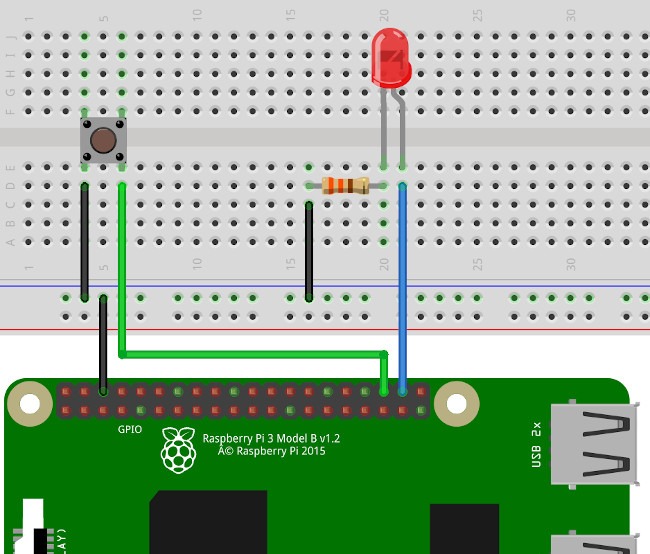
How to make this circuit:
- Make sure your Raspberry Pi is powered off whenever you setup or modify your circuit.
- Connect all components to the Pi ground. Add a resistor (330 Ohm here) between the shorter leg of the LED and the ground, to protect the LED.
- Connect one leg of the button to GPIO 16 (keep the 2 other legs independent), and the longer leg of the LED to GPIO 20.
The hardware setup is ready (more info on Raspberry Pi pinout if you need), now let’s continue with the software setup.
If you haven’t installed ROS on your Pi yet, check out how to install Ubuntu Mate, and how to install ROS.
Connect to your Pi via ssh. If you don’t know how to do this, follow the tutorial on how to install Ubuntu on your Pi.
Everything is ready, let’s now write the code!
ROS Service server on Raspberry Pi
We’ll start with the server. The goal of the server will be to receive requests from the client, and power on/off the LED accordingly.
In your catkin workspace, create a new Python file in the scripts/ folder of one of your packages (we’ll use “rpi_ros_tutorials” as package name for this tutorial). Make this file executable.
$ touch led_service_server.py
$ chmod +x led_service_server.py
The code
#!/usr/bin/env python

import rospy
from std_srvs.srv import SetBool
import RPi.GPIO as GPIO

LED_GPIO = 20

def set_led_state_callback(req):
    GPIO.output(LED_GPIO, req.data)
    return { 'success': True,
            'message': 'Successfully changed LED state' }

if __name__ == '__main__':
    rospy.init_node('led_actuator')

    GPIO.setmode(GPIO.BCM)
    GPIO.setup(LED_GPIO, GPIO.OUT)

    rospy.Service('set_led_state', SetBool, set_led_state_callback)
    rospy.loginfo("Service server started. Ready to get requests.")

    rospy.spin()

    GPIO.cleanup()
Let’s break down this code line by line.
Imports and GPIO setup
#!/usr/bin/env python

import rospy
from std_srvs.srv import SetBool
import RPi.GPIO as GPIO

LED_GPIO = 20
First we import what we’ll need in our program. For the service we’ll create we need to choose a data type, or in ROS terms, a “service definition”. We’ll use an existing ROS service definition, std_srvs/SetBool, as it fits our needs. If this import line fails, maybe the std_srvs package was not installed on your machine, you can fix that with sudo apt install ros-melodic-std-srvs.
if __name__ == '__main__':
    rospy.init_node('led_actuator')

    GPIO.setmode(GPIO.BCM)
    GPIO.setup(LED_GPIO, GPIO.OUT)
The first thing we do on the program is to initialize the node (we’ll look at the callback function just after finishing with the main). Then we setup the LED GPIO as an output pin, in order to be able to change its state.
Initializing the service server
    rospy.Service('set_led_state', SetBool, set_led_state_callback)
    rospy.loginfo("Service server started. Ready to get requests.")
We can now create the service server with rospy.Server(). You need to give 3 arguments:
- Name of the service. You will use this exact same name on the client code to be able to reach the server.
- Service definition (don’t forget to import it in your program). This is the data type you’ll use to exchange information between the client and the server.
- Callback which will be triggered when the server receives a client request.
After that we add a simple log line so we have a hint on when the server is up when we start the node in a terminal.
rospy.spin()
This will make the program “pause” until you kill the node (for example with CTRL+C). It will also handle all the callbacks in the background, so it’s very important you don’t forget it if you want your service to work.
GPIO.cleanup()
After you kill the node, rospy.spin() will exit. It’s the perfect time to do a little bit of cleanup with GPIO.cleanup(). This function will restore the default state for any pin used in this program. This is very important in this case since you’ve set a pin as output. Letting an output pin can burn your Pi if you make a wrong hardware connection (especially if the pin’s state is HIGH).
Service server callback
def set_led_state_callback(req):
    GPIO.output(LED_GPIO, req.data)
    return { 'success': True,
            'message': 'Successfully changed LED state' }
This is the service server callback. Every time a client sends a request to the server, this function will be called. That’s where you’ll handle the client request, which you get as a parameter.
Now, if you look at the SetBool definition, you can see that the request contains only one field, named “data”. We can then access it simply by writing “req.data”, and power on/off the LED accordingly.
The client will expect the server to send a response. That’s what the second part of the definition is for. There are 2 fields: “success”, a boolean, and “message”, a string. In this case we can send back a Python dictionary and fill all the required fields. For that example, the server always succeed in changing the LED’s state. If your server has an uncertain outcome, you can send a failure message if needed, so the client will know what happened.
Now, time to write the client side!
ROS Service client on Raspberry Pi
The client’s goal is to monitor the button’s state, and when pressed or released, send a request to the LED service server.
Create another Python file, for another node, in your scripts/ folder of the same package. Make it executable.
$ touch button_service_client.py
$ chmod +x button_service_client.py
The code
#!/usr/bin/env python

import rospy
from std_srvs.srv import SetBool
import RPi.GPIO as GPIO

BUTTON_GPIO = 16

def button_callback(channel):
    power_on_led = not GPIO.input(BUTTON_GPIO)

    rospy.wait_for_service('set_led_state')
    try:
        set_led_state = rospy.ServiceProxy('set_led_state', SetBool)
        resp = set_led_state(power_on_led)
    except rospy.ServiceException, e:
        rospy.logwarn(e)

if __name__ == '__main__':
    rospy.init_node('button_monitor')

    GPIO.setmode(GPIO.BCM)
    GPIO.setup(BUTTON_GPIO, GPIO.IN, pull_up_down = GPIO.PUD_UP)

    GPIO.add_event_detect(BUTTON_GPIO, GPIO.BOTH,
            callback=button_callback, bouncetime=50)

    rospy.spin()

    GPIO.cleanup()
As we did for the server, let’s break down the client code line by line.
Imports and GPIO setup
#!/usr/bin/env python

import rospy
from std_srvs.srv import SetBool
import RPi.GPIO as GPIO

BUTTON_GPIO = 16
You can see that we have the exact same imports as for the server. The important line here is related to SetBool. Whenever you use a Service, both client and server should use the same service definition in order to talk to each other.
if __name__ == '__main__':
    rospy.init_node('button_monitor')

    GPIO.setmode(GPIO.BCM)
    GPIO.setup(BUTTON_GPIO, GPIO.IN, pull_up_down = GPIO.PUD_UP)
We initialize the node first thing, and then setup the button GPIO mode to input. Also we activate the internal pull up resistor of the Raspberry Pi for this pin, so default state will be HIGH. When you press the button, the state will change to LOW, and when you release it, it will come back to HIGH.
    GPIO.add_event_detect(BUTTON_GPIO, GPIO.BOTH,
            callback=button_callback, bouncetime=50)
We add an interrupt on the button GPIO, for both rising and falling events. This means that as soon as the button is pressed or released, an interrupt will be triggered, and the callback function will be called. Using interrupts with the RPi.GPIO module is very handy for what we need to do here. If you want to know more about interrupts and this particular function, check out this Raspberry Pi GPIO interrupts tutorial.
    rospy.spin()

    GPIO.cleanup()
Finally, in the main, as we did for the server, we use rospy.spin() to wait until the node is killed. And before the program exits, we do a little bit of GPIO cleanup.
Calling the service server from the client
This will all happen in the GPIO interrupt callback.
def button_callback(channel):
    power_on_led = not GPIO.input(BUTTON_GPIO)

    rospy.wait_for_service('set_led_state')
    try:
        set_led_state = rospy.ServiceProxy('set_led_state', SetBool)
        resp = set_led_state(power_on_led)
    except rospy.ServiceException, e:
        rospy.logwarn(e)
When an interrupt is triggered, the button_callback() function will be called. From that function, we use a service client to immediately reach to the server, in order to actuate the LED. Note: make sure not to have any confusion between the service server callback (ROS mechanism) and this GPIO interrupt callback (nothing to do with ROS at all, it’s just about interrupts).
Let’s break down this piece of code even further:
def button_callback(channel):
    power_on_led = not GPIO.input(BUTTON_GPIO)
First thing we do in the interrupt callback is to read the button’s state to know if we need to power on or off the LED.
rospy.wait_for_service('set_led_state')
This function will, as its name suggests, wait for the ROS service to be up. This can be useful when you launch all your nodes at the same time. In this case the server might be ready just after the client, and thus the client’s request will be lost if you don’t wait a little bit.
    try:
        set_led_state = rospy.ServiceProxy('set_led_state', SetBool)
Inside a try/catch structure, you can create a client with rospy.ServiceProxy(). You’ll need to give 2 arguments:
- Name of the service. This needs to be the exact same as the name you defined on the server side.
- Service definition. Also needs to be the same as for the server, so both can understand each other.
resp = set_led_state(power_on_led)
Then you can actually send your client request, and receive a response. Here we just give a boolean value as a parameter, since that’s the only field required for the request. The rospy library will then, under the hood, create a complete request message, send it to the server, wait for the server to answer, and finally return the server response into the “resp” variable.
In this tutorial we don’t use this response, but in some situations you’ll need to do that. The response here will contain a “success” and “message” fields, filled by the server. You can use rospy.loginfo(resp) to quickly see what’s inside.
    except rospy.ServiceException, e:
        rospy.logwarn(e)
If the service call failed, we’ll get an exception that we’ll catch here. Important note: if you get an exception, it means that the ROS service mechanism failed. If, for example, you send a request to the server, the server receives it, decides (from the code you wrote) that it won’t change the LED’s state, returns an error code to the client, then in this situation, the service still succeeded, since the communication succeeded.
So, you’ll mostly get an exception when the server is not up, or if something is wrong in your ROS graph, or if your server code is not correct (syntax error, exception in the server callback, …).
Testing the ROS Service on your Raspberry Pi
Test the application
Let’s now test both the server and client on your Raspberry Pi.
It’s best to open several ssh terminal so you have at least one to write the code, one to start roscore, one for each node that you’re launching + one for testing stuff with command line tools.
- First, start
roscore. - Run the server with
rosrun rpi_ros_tutorials led_service_server.py. - Run the client with
rosrun rpi_ros_tutorials button_service_client.py.
Now, press the button. If everything went well, the LED should be powered on! And when you release the button, the LED should be powered off.
You can see both nodes on your ROS environment:
$ rosnode list
/button_monitor
/led_actuator
/rosout
And you can also check that the service you created in on the service list:
$ rosservice list
/button_monitor/get_loggers
/button_monitor/set_logger_level
/led_actuator/get_loggers
/led_actuator/set_logger_level
/rosout/get_loggers
/rosout/set_logger_level
/set_led_state
Here it is: /set_led_state. As you can see, a leading slash was automatically added to it, for namespace purposes.
Debug your Raspberry Pi ROS service
Here are some steps you can follow if your application is not working (or if you just want to practice with command line tools and debugging).
Of course, make sure to double-triple check your hardware.
If the hardware is not faulty, start with the server only. Launch it and see if you can power on/off the LED directly from a terminal, with the rosservice command line tool.
$ rosservice call /set_led_state "data: true"
success: True
message: "Successfully changed LED state"
$ rosservice call /set_led_state "data: false"
success: True
message: "Successfully changed LED state"
If you don’t see the LED’s state change, and don’t get those log lines on your terminal, then something is wrong inside your server.
First, test that the LED can work correctly. Test only the RPi.GPIO parts of your code, and remove the ROS stuff. Once done, add some log line inside your service server callback to see what’s wrong. For example, you can print the request with rospy.loginfo(req). This will help you find the source of the problem. And usually, after you find the source, solving the problem becomes much easier.
Don’t hesitate to add a lot of logs to see what’s happening in different parts of your code. Once you’ve fixed the issue you can remove the unnecessary logs.
Then, you can do the same with for client. If you’re sure that the server is working correctly, repeat the same steps for the client to find any possible issue to fix.
Going further with Raspberry Pi and ROS
With this tutorial you’ve learned how to create a complete Python ROS service (server + client) on your Raspberry Pi, using the GPIO header to actuate some real hardware.
If you haven’t done it before, make sure to check how to write a Publisher / Subscriber on your Raspberry Pi, also using GPIOs. This series of tutorials will give you a good starting point to create more complex applications.
And now, if you want to go further, well… I strongly advice you find a personal project to work on. Build a robot with ROS installed on an embedded Raspberry Pi, you’ll see, that’s a lot of fun, and you’ll learn so much!
